|
|
HISTORICAL MINIATURES BY GEORGE GRASSE |
|
|
|
HISTORICAL MINIATURES BY GEORGE GRASSE |
|
|
SPAD 7 Sp.1, 5eme Escadrille, S/Lt. Edmond Thieffey, Aeronautique Militaire Belge 1917 |
by George Grasse
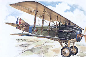
SPECIAL HOBBY 1:48 SCALE INJECTION KIT SO4010 of the SPAD 7 in BELGIAN SERVICE
|
SPECIAL HOBBY SO4010 BOX ART
|
 |
|
SPAD 7 THREE-VIEW DRAWING
|
%20small.jpg) |
|
This 3-view drawing is reproduced from the Harleyford
publication Fighter Aircraft of World War 1. The French-built
Spad 7 arrived in Belgian service after much wrangling and was
issued to Escadrile 5eme Belge. S/Lt Edmond Thieffry recieved
the first one, serial number Sp.1. To Belgium were delivered barely enough Spad 7 and Spad 13 fighters to equip the 5eme Escadrille Belge. The other principal Belgian fighter squadron was equipped exclusively with the Hanriot HD.1 |
|
THE
MODEL TO BE BUILT
|
%20x700.jpg) |
| The model to be built is Spad 7 No. Sp.1 assigned to S/Lt Edmond Thieffry of the 5eme Escadrille Belge. This Spad 7 was finished in the standard French "yellow" scheme. After delivery, the upper surfaces appear to be some sort of olive green. The flying comet was the insignia of the escadrille. All other markings were for Thieffry. Consult the bibliography below. He scored victories 7 - 10 in the Spad 7. This image was produced by Harry Dempsey and appeared in the Osprey Aircraft of the Aces No.39, Spad VII Aces of WW1, plate 30 on page 56. |
.jpg)
.jpg) |
| S/Lt Edmond Thieffry who probably wrecked more Belgian aircraft than those of the enemy. |
|
CONSTRUCTION PHOTO No.1 |
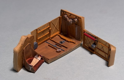 |
| As always, construction starts with the interior cockpit. The component with the pilot's seat will enclose the cockpit rear. The "wall" with the red pump swings to meet the seat creating a rectangular cockpit box. |
|
CONSTRUCTION PHOTO No.2 |
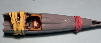 |
| before sealing the two fuselage halves, the cockpit was further built-up with the "shelf" which holds several instruments and (partially obscured) the instrument panel. Several trial fittings were done and some trimming was necessary. Then, the cockpit assembly was placed (not glued) between the two fuselage halves which were glued and binded together with rubber bands. |
.jpg) |
| I present this photo taken fron The Belgian Air Service in the First World War, page 394, to show the radiator and the propeller mounting plate. The Special Hobby kit supplies three slightly different cowling/radiator pieces. This photo helped determine which to use. |
|
CONSTRUCTION PHOTO No.3 |
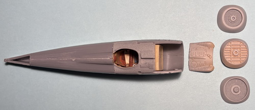 |
| This photo shows the assortment of front cowling pieces in the kit. |
|
CONSTRUCTION PHOTO No.4a and 4b |
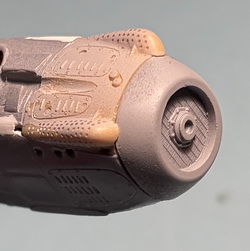
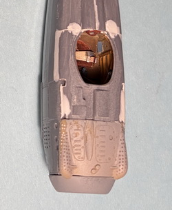 |
| The front piece I chose closely resembles the one in the photo above. Vallejo Plastic Putty is used liberally to fill gaps. More will be needed here. |
|
CONSTRUCTION PHOTO No.5 |
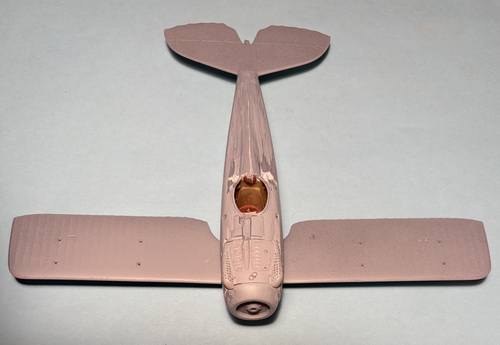 |
| The fuselage has been patched with putty and primed. The lower wings had two brass pins per wing installed and then glued to the fuselage. The horizontal tail as glued last. |
|
CONSTRUCTION PHOTO No.6 |
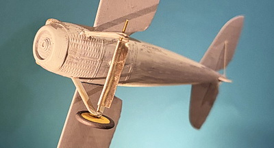 |
| The The landing gear struts were built from brass tube and rod fashioned into "V" shape. The axle is brass rod with the aerfoil made from sheet lead. The tail's struts are brass rod and the tail skid is brass tube and rod flattened and cut to length. |
|
CONSTRUCTION PHOTO No.7 |
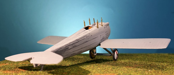 |
| Four fuselage struts were made from brass tube and rod by copying the kit's plastic struts for the net length. The brass rods were much longer to serve as attachment points. There is a fifth rod amongst the struts and is the radiator water pipe leading to the underside of the top wing. |
|
CONSTRUCTION PHOTO No.8 |
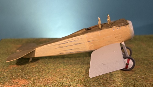 |
| Belgium received a small alottment of Spad 7s which were furnished in current French "yellow" scheme, basically all fabric was clear doped and all wood/metal parts were matched with another paint closely matching the fabric. One problem I discovered early on was the darker shade apparently covering top surfaces. For whatever reason, the Belgians probably used the most available paint, namely British PC10 or PC12. I chose to use my mix of PC10. What is shown in this photo is a rough application to the fuselage. |
|
CONSTRUCTION PHOTO No.9 |
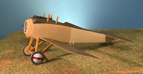 |
| The fuselage has its final coat of three colors all of which are my own pre-mixed shades: light yellow, dark yellow, and PC.10. The lower wing has received its first coat of PC.10. |
|
CONSTRUCTION PHOTO No.10 |
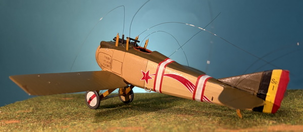 |
| The cross wires on the fuselage top deck are added now to be glued up and across the fuselage struts and then down to corresponding wing struts after the top wing is glued in place. The fuselage bands were improvised from white decal paper cut to width and applied. Next, thin strips of red decal paper were cut and applied. The comet insignia was a problem. I tried photo copying and editing a set but they did not come out right. I noticed that a pair of comets was included in my Eduard Hanriot HD./2 kit and I used those. The tail number "Sp 1" was made in Word and printed on laser clear decal paper. |
|
CONSTRUCTION PHOTO No.11 |
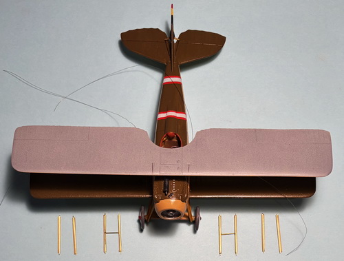 |
| The top wing has been securely glued to the fuselage struts. To make the wing eight wing struts, I first measured then cut eight brass rods slightly longer to account for the attachment to the wings. Four 1.3mm OD brass tube struts were cut, slightly shorter than the rods. The inside wing struts required extra work because of the cross bar, the exact length of which is 3/8". The are two ways to make holes in each strut to accomodate the cross bar: 1) use a No.72 drill bit in your hand vise and carefully drill out the hole which is tricky because the strut can roll away from you, and 2) using a brand new sharp X-Acto blade, literally punch a hole through the 1mm tube's brass wall, and round it out a bit with a little twisting to widen the hole. Use super glue to attach each cross bar to the center of each strut and let the "sub-assembly harden. Take one of the previosly cut tubes, add some super glue, and carefully insert one end of the cross bar into the hole. When dry, add the other strut to the cross bar. After all of that is done, drop one of the leftover brass rods into each end of each strut. The cross bar will prevent the rod from going all the way through so cut off the excess leaving just enough to fit into the corresponding holes in the wings. |
|
CONSTRUCTION PHOTO No.12 |
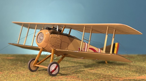 |
| Each pair of struts with the cross bar is attached to the wings first. Check for alignment into the pre-drilled holes. Dry fitting before gluing is recommended. When completely dry, attach one set of outside struts to one side. Again, check for alignment. You may have to trim the brass rod to get a perfect fit. |
|
CONSTRUCTION PHOTO No.13 |
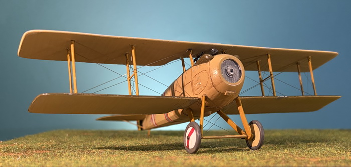 |
| All rigging is completed: wing, fuselage, landing gear, and rudder. I made the costly error of not prepainting the struts and their binding tapes. I had to work around all of the rigging to complete priming and painting along with a lot of corrective work. The binding tapes are next. |
|
CONSTRUCTION PHOTO No.14 |
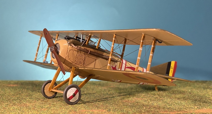 |
|
CONSTRUCTION PHOTO No.15 |
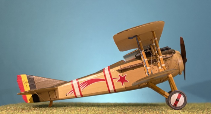 |
|
CONSTRUCTION PHOTO No.16 |
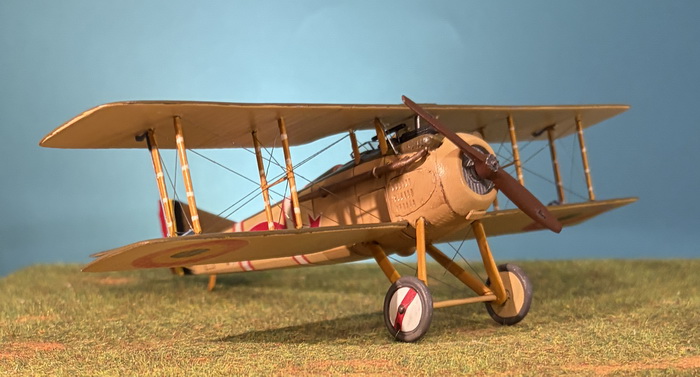 |
|
CONSTRUCTION PHOTO No.17 |
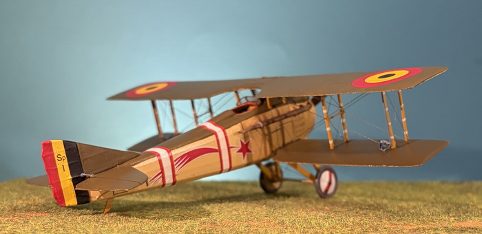 |
|
CONSTRUCTION PHOTO No.18 |
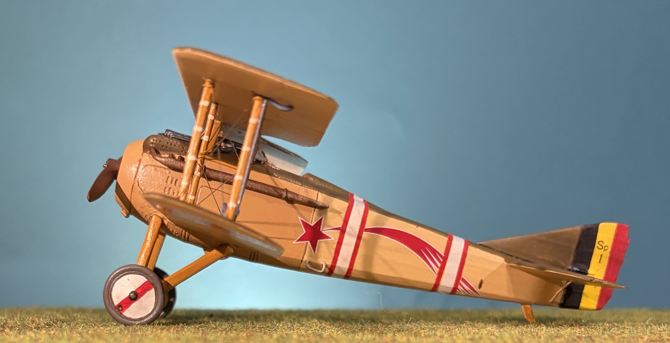 |
|
CONSTRUCTION PHOTO No.19 |
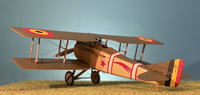 |
------------------------------------------- finis ---------------------------------------
Bibliography:
Bruce, J. M. Spad 7.C1, Windsock Datafile 8. Berkhamsted, Herts: Albatros Productions, 1988.
Bruce, J. M. Spad Scouts SVII - SXIII. Glencoe Models via Osprey Publications.
Conners, John F. SPAD Fighters in Action. Carrollton, Texas: Squadron-Signal Publications, 1989.
Franks, Norman, Russell Guest, and Gregory Alegi. Above the War Fronts. London, UK: Grub Street, 1997
Davilla, James J. Dr. and Arthur M. Soltan. French Aircraft of the First World War. Boulder, CO, Flying Machines Press, 2002.
Guttman, Jon. Spad VII Aces of World War I, Osprey Aces No.39. Oxford, UK, 2001.
Lamberton, W. M., Compiler, and E. F. Cheesman, Editor. Fighter Aircraft of the 1914-1918 War. Los Angeles, CA: Aero Publishers, 1962.
Pieters, Walter M. Above Flanders Fields. London, UK: Grub Street, 1998.
Robertson, Bruce Editor. Air Aces of the 1914-1918 War. Garden City Press, UK: Harleyford, 1959.
Velek, Martin. Spad VII C1. Prague, Cz: 4+Publication (Mark I Ltd), 2004.
GO TO?
15 August 2026
