|
|
HISTORICAL MINIATURES BY GEORGE GRASSE |
|
|
|
HISTORICAL MINIATURES BY GEORGE GRASSE |
|
| ROYAL AIRCRAFT FACTORY FE.2b, 6994, No.11 Squadron, RFC, 1916 |
by George Grasse

|
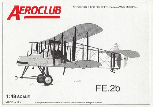
AEROCLUB ACK417 1:48 SCALE MULTI-MEDIA KIT ACK417 of the RAF FE.2b |
|
AEREOCLUB ACK417 BOX ART
|
 |
|
RAF FE.2b 3-VIEW DRAWING
|
.jpg) |
| This 3-view drawing is credited to J. D. Carrick or F. Yeoman and appeared in Fighter Aircraft of the 1914-1918 War page 45, compiled by W. M. Lamberton and published by Harleyford Publications Limited. Pusher aircraft were thought to be the temporary solution to forward-firing machine guns. The large FE.2 pusher series were intended as "fighting" aircraft much in the vein of Vickers' FB.5 "Gunbus". Variously armed with two or three Lewis machine guns on pedestal mounts, the FE.2b was noetheless a dangerous opponent though somewhat easy prey especially to then-modern German biplane fighters such as the Albatros D series. The FE.2b went on in traditional corps reconaissance duties especially as a photo and recon aircraft. |
%20x700.jpg) |
| Royal Aircraft Factory (RAF or R.A.F.) FE.2b serial 6994 "Montreal No.3" was flown by Captain Stephen W Price (p) and Lt. Frederick Libby (0) of RFC No.11 Squadron, France 1916. Price scored seven victories during the war as a pilot and Libby scored an astonishing 14 victories of which 10 were on the FE.2b. Additionally, Libby was a Colorado-born American who actually became the first U.S. ace of World War 1. |
|
CONSTRUCTION PHOTO No. 1
|
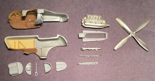 |
| Getting all the nacelle parts out of the box and starting. I downloaded one of the Wingnut Wings instruction manuals for the FE.2b to get a better view of assembly and painting. I glued one piece into place and started painting the interior. I'll build up the instrument panel with Eduard instruments and other instrument decals using the Wingnut Wings photos. |
|
CONSTRUCTION PHOTO No.
2
|
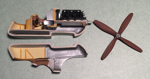 |
| This photo shows progress on the FE.2b nacelle, mainly the engine and nacelle interior. I used Wingnut Wings' instrution manual for botht the FE.2b early and late. |
|
CONSTRUCTION PHOTO No.
3
|
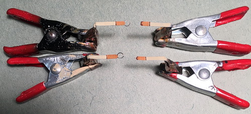 |
| One of the prominent features in the nacelle are the drapping of the seatbelts for both the pilot and observer. I cut four lengths of "wine bottle" lead foil, primed, and painted in beige white for the belt and leather brown for the reinforced ends. To the underside of two of the belts I glued the ends of PE beltswith the steel loop. Holes were indented into the leather portion using a simple straight needle. |
|
CONSTRUCTION PHOTO No.
4
|
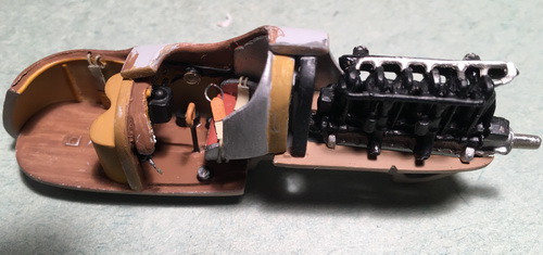 |
| Quite a bit of work went into the progress you see in the above photo. I consulted the Wingnut Wings instructioins for detail of the nacelle interior and added the seatbelts, rudder return pulleys, air pressure pump, magneto, piping for instrument sensors, control column and touch-up painting. |
|
CONSTRUCTION PHOTO No.
5a, b, c
|
 |
 |
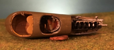 |
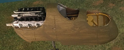
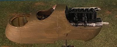
| These three images show the closure of the fusealge halves with a single coat of my Vallejo PC.10 mix. |
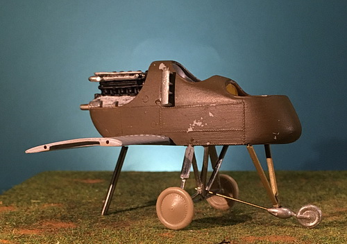 |
| The air cooling intakes (white metal parts) were glued to the side of the pilot's cockpit. The center section of the lower wing was cleaned up and glued to the bottom of the nacelle. The landing gear sub-assembly was challenging. All of the kit's white metal parts were used except the lower brass rod and the forward brass tube and rod struts. |
|
CONSTRUCTION PHOTO No.
7
|
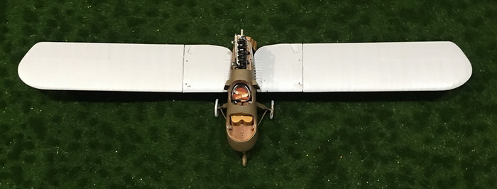 |
| The outer panels of the lower wing had two additional brass pin inserts set on either side of the tabs that fit into the mid-wing section. Super glue was used for adhesion. Alighnment was carefully observed. Additional finishing (putty, sanding) has not yet been done. |
|
CONSTRUCTION PHOTO No.
8
|
 |
| The top wing is three sections and joined with large tabs on the underside. I added brass pins for additional strength. A fair amount of plastic putty was needed for all joints. |
|
CONSTRUCTION PHOTO No.
9
|
| Before continuing on, we need to review the color profile. Notice the position of the landing gear struts especially the rear which is aligned with the wing struts: (click here). Now, review the alignment in Phot0 No.6 which is incorrectly advanced well beyond the wing edge: (click here). This panel (Photo No.9) shows the now corrected alignment below. |
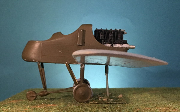 |
| The basic assembly of the entire landing gear strutcture was preserved with the exception of the second set of struts which were replaced with brass tube and rod struts. The rear struts were repositioned in the correct position as marked on underside of the nacelle (which I originally overlooked). A lot of bumping around during this process has left several scratches here and there. |
|
CONSTRUCTION PHOTOS No.
10a & 10b
|
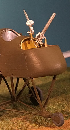 |
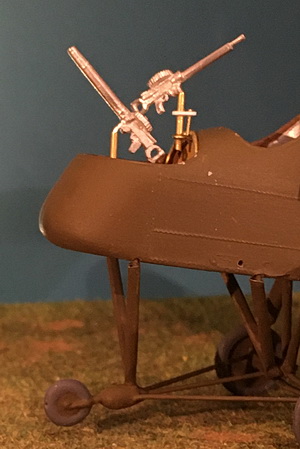
| This step in the building process was a bit time-consuming. The front pedestal mount was okay. The metal projection of the Lewis Gun fit into a 1.0mm brass tube which itself fit into a 1.3mm brass tube cemeted to the cockpit floor. The rear Lewis Gun took a bit of engineering. First a support ring was added which reaches to the cockpit floor. Second, a small brass ring was glued to take the pedestal mount. The mount itself is fitted with a flanged collar to accept the mounting tube and supporting rod. |
|
CONSTRUCTION PHOTO
No.11
|
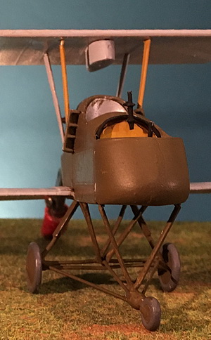 |
| The fuselage wing struts are fabricated from brass tube and rod, set in place for trial fits, then glued and allowed to dry. The top wing is carefully glued to these struts. The red object at rear is an alligator clip I use to prop up the model. |
|
CONSTRUCTION PHOTO
No.12
|
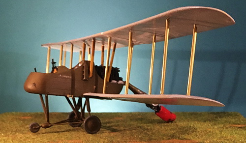 |
| Finally, all of the 12 wing brass rod and tubing wing struts are in place. Several 'gremlin' attacks caused damage to the model especially the top wing which seriously delayed getting the struts in place. Rigging will have to be next to hold the two wings together even though super glue was used. |
|
CONSTRUCTION PHOTO
No.13
|
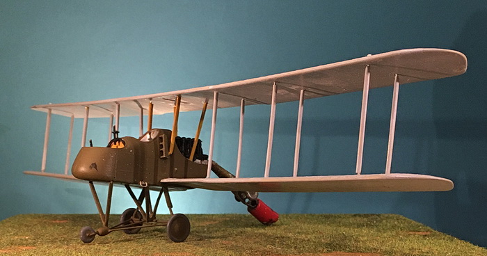 |
| In preparation for the complex rigging step, the struts have to be primed and painted. This photo shows the priming stage. The blemish on the nacelle is from my swerling paint brush. The small white objects on the top wing above the outside front strut is the return pulley for the ailersons. |
|
CONSTRUCTION PHOTO
Nos.14a through 14e
|
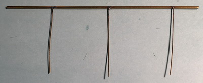 small diameter rod soldered into holes of each boom top 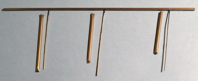 corresponding struts lined up 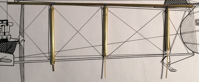 tops of struts placed into position - excess rod to be cut off 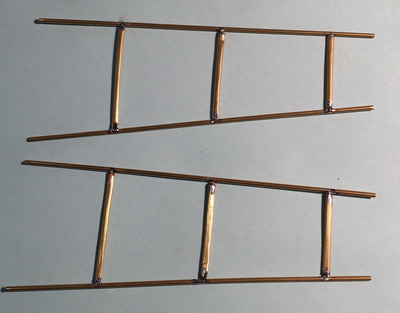 bottom of rods soldered to boom's lower piece 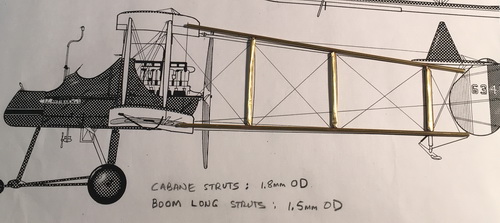 completed boom shown against kit's drawing |
| Some of the major steps in produring the completed left and right booms. |
|
CONSTRUCTION PHOTO
No.15
|
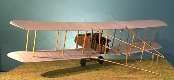 |
| The completed tail boom skeleton is attached to the wings using brass pins passing through the ends of each boom, through the corresponding wing, and soldered. The underside of each wing's pin was trimmed and then bent flat. Additionally, the tail end of each left and right boom sub-assembly was filled with a "U" shaped brass rod and soldered in place. |
|
CONSTRUCTION PHOTO
No.16
|
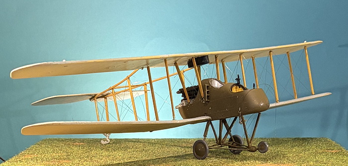 |
| The right side of the wing set has been compromised by oversize struts that distorted the alignment of the tailboom. All right side wing struts were removed including any rigging that was attached. The mis-alignment was caused by over size struts next to the nacelle and incorrect positioning of the bottom of eavh strut nearest the nacelle. The proper attachment holes were re-drilled closer to the nacelle and allowed for the properly-sized struts to be positioned as shown. You can see that the right lower wing is angled upward too much but this can be corrected with properly sized struts. |
|
CONSTRUCTION PHOTO
No.17
|
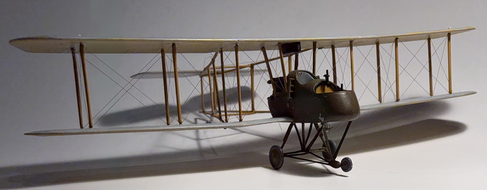 |
| The right side of the wing set has now been completely restored including new rigging. Construction can now continue. |
|
CONSTRUCTION PHOTO
No.18
|
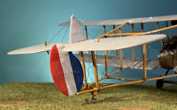 |
| All of the tailboom rigging has been restored. This photo shows work on the tail unit. The triangular fin was glued in place. Pre-drilled holes were used to stabilize it all in one long piece of .006 MFL. Next, conftrol horns were added to the horizontal and vertical parts. Lastly, at this stage, the rudder was glued in place. |
|
CONSTRUCTION PHOTO
No.19
|
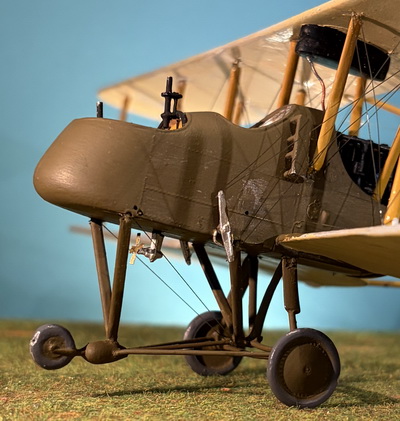 |
| The elevator rigging is complete all the way back to the tail but not shown. The foot step is in the wrong position and will be moved to the left. The wind-driven pump was a kit item but the propeller came from an Extra Tech PE sheet. The small hole just behind the elevator control rocker arm is the entrance for the port aileron rigging soon to be addressed. Holes above and to the right of the forward landing gear strut are for two drift wires. |
|
CONSTRUCTION PHOTO
No.20
|
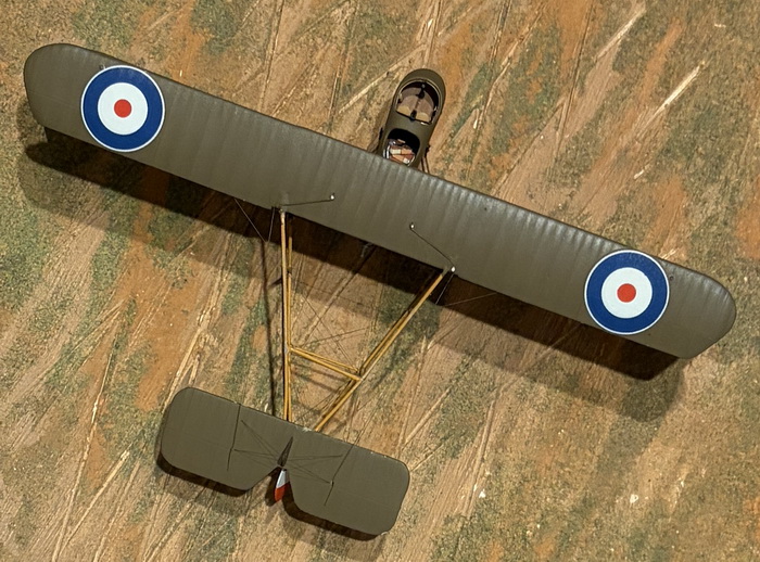 |
| The overall topside finish is my rendition of British PC.10. It's a 50-50 mix of Vallejo 887 Brown Violet and 983 Flat Earth. I was surprised at the excellent condition of the kit's decals being at an advanced age. The white "dots" on the wing are represent pulleys guiding the elevator wires that eventually end up going through each side of the nacelle. |
|
CONSTRUCTION PHOTOS
No.21 a thru e
|
 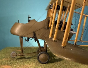
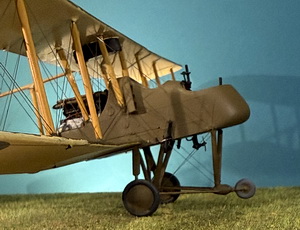 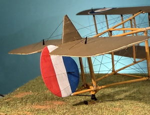
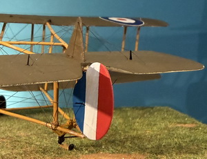 |
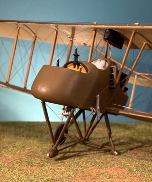
| The top photo shows that all the existing wheels were removed, reinforced with brass rod, and replacement main wheels (results shown in next two photos). The front side view photos show a number of additions including the rudder rocker bar, the underside wind-driven generator, the two drift wires on each side, and the final touchup coat to the top wing's underside. The bottom two photos show the tail rigging for the rudder and for the elevators. The triangular vertical stabilizer is supported by two wires on each side. The tail skid is now painted. All of the pre-disaster tail boom rigging has been replaced and enhanced with additional rigging. |
