|
|
HISTORICAL MINIATURES BY GEORGE GRASSE |
|
| SOPWITH PUP N.6205, No.3 SQDN, Flight Commander 'Joe' Fall, RNAS, 1916 |
by George Grasse

|
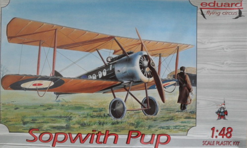
EDUARD 1:48 SCALE PLASTIC INJECTION KIT EU8011 of the SOPWITH PUP |
|
EDUARD EU8011 BOX ART
|
|
|
|
SOPWITH TRIPLANE 3-VIEW DRAWING
|
![]() |
| This 3-view drawing is credited to J. D. Carrick or F. Yeoman and appeared in Fighter Aircraft of the 1914-1918 War compiled by W. M. Lamberton and published by Harleyford Publications Limited. The introduction of the Sopwith Pup in early 1916 represented the first British tractor biplane with a syncronized machine gun that blunted the run-away success of Germany's Albatros D-type biplane fighters. The balance of air power was more or less equalized with the addition of the Sopwith Triplane introduced at about the same time. |
|
THE
MODEL TO BE BUILT
|
![]() |
| Sopwith Pup N.6205 "Betty" was flown by Flight Commander Joseph 'Joe' S. T. Fall of RNAS Squadron No.3, France 1917. He scored three victories of his 11 'Pup' victories and went on to score 25 more flying the Sopwith 1F.1 'Camel' for a total score of 36. The 'Pup' was powered by a variety of rotary engines ranging from the 80 hp to 110 hp. Its armament was a single .303 Vickers machine gun. There were eight operational 'Pup' squadrons in France: 48, 54, 66 RFC; 3, 4, 8, 9 Naval (RNAS), and one of the Dunkirk-based Seaplane Defence Flight. At the time of its introduction in the early fall of 1916, the Fokker Eindeckers had been chased away and the 'Pup' came up against the various interim German biplane fighters that preceded the full-scale introduction of the Albatros D Series, mostly Fokker and Halberstadt D biplanes. By October 1916 the main 'Pup' adversary was the Albatros D.II followed by the D.III. Nonetheless, 'Joe' Fall's 11 victories included one Halberstadt D.II, two unknown seaplanes, three Albatros D.II, four Alabtros D.III, one early Albatros D.V. |
|
CONSTRUCTION PHOTO No. 1
|
|
|
| Starting off with the cockpit interior and rotary engine. Upper left, cockpit floor with rudder bar, seat, and harnesses. Vickers machine gun with butt frame, gun, and ammunition box. Frame of the cockpit interior. Second row includes the instrument panel and rotary engine in cowling. Other miscellaneous parts scattered about. |
|
CONSTRUCTION PHOTO No.
2
|
|
|
| Building up the cockpit interior as with all early Eduard kits that are heavily in to PE parts was difficult folowed by the difficult step of gluing the fuselage halves together worrying about the flimsy cockpit interior parts. Well, I got through it and added the horizontail tail unit and lower wing. The underside of the fuselage did not match drawings and took a lot of putty to make the underside one continuous piece. |
|
CONSTRUCTION PHOTO No.
3
|
|
|
| Brass replacement parts are shown above. The landing was completely re-built using brass tube and rod for the struts, brass rod for the axle, and lead sheet for the airfoil. The tail skid was a cut-down version of a previously built strut of brass tube and rod, flattened, but to size, and glued into position. Additional putty is applied to smooth out the undrside. |
|
CONSTRUCTION PHOTO No.
4
|
|
|
| The metal-cast rotary engine was trimmed up and had copper intake 'pipes' added from the PE sheet. Engine was painted and inserted into the cowling then both were glued to the fuselage as shown. The underside was painted with one coat of Vallejo 976 Buff but I might tone it down using Vallejo 917 Beige. The Vickers MG was glued to the top centerline. I discarded the kit's plastic cabane struts and made my own with brass rod and 1.4mm brass tubing. This is a simple biplane to build and paint but this early Eduard kit from the previous century featured a brass PE sheet that contained all of the parts to build up the cockpit interior. In this particular case, I had nothing but trouble putting it all together. I don't think I'll venture into another similar type kit again. |
|
CONSTRUCTION PHOTO No.
5
|
|
|
| Fuselage details have been worked out in this photo. Two coats of my PC.10 mix were applied first to include the landing gear. The top decking from the front of the cockpit to the cowling including the wheel covers was painted with Vallejo 947 Dark Vermillion. The rest of the decking to behind the cockpit, which is plywood, was first painted in Vallejo 874 Tan Earth and carefully streaked with two different colors to simulate the wood grain. The cockpit coaming was painted in Vallejo 818 red Leather. The vertical stabilizer was pre-painted before attachment. The forward portion was painted in Vallejo 917 Beige. The rudder stripes wee hand-painted. As for fuselage decals, I started with "BETTY", then the cockade, then the white stripe, then the "Lift Here" signs, and lastly, with the "Sopwith" logo on the vertical fin. |
|
CONSTRUCTION PHOTO No.
6
|
|
|
| The attachment of the top wing was preceded by the separate gluing of all of the .006 MFT thread. These were then taped aside and the top wing was glued to brass struts. The tailskid is flattened brass tube with a brass rod insert. |
|
CONSTRUCTION PHOTO No.
7
|
|
|
| The wing struts were glued next with super glue. All of the loose, dangling "wires" were carefully attached four or six at a time. Each was passed through its corresponding hole in the lower wing, clipped, and allowed to dangle under weight until dry. When finished, the underside of the lower wing was sanded smooth and painted over. Note the PE Pitot tube attached to the upper right front strut. |
|
CONSTRUCTION PHOTO No.
8
|
|
|
| This finished photo illustrates the attachment of the wing aileron control wires. An Eduard PE control horn is glued into pre-marked holes. The .006 MFT thread is glued to the upper wing into a small hole forward of the control horn. When dry, it is passed through the horn then down and through a hole to the rear of the aileron. It continues through the bottom wing passing through another control horn and then into a hole forward. |
|
CONSTRUCTION PHOTO No.
9
|
|
|
| This view of the completed model shows the right aileron rigging and the Pitot tube attached to the forward right wing strut. Note the Pitot tube attached to the upper right front strut. |
|
CONSTRUCTION PHOTO No.
10
|
|
|
| In this view the rigging of the tail control surfaces is shown. In addition, stabilizing wires were attached to the rudder, through corresponding holes in the horizontal stabilzer, and then into the fuselage at its bottom. The rudder control horn is not visible in this photo and has a relatively short run into the fuselage. |
|
CONSTRUCTION PHOTO No.
11
|
|
|
| This right three quarter view illustrates all of the various rigging lines. |
|
CONSTRUCTION PHOTO No.
12
|
|
|
| Barely visible is the padded windscreen. The kit supplied a flat PE piece to which I glued (in several sittings) Vallejo plastic putty, all around the the outside perimeter. Eventually, enough material had been applied and, with some sanding, the finished product of a padded windscreen came out better than expected. The front side had the actual clear plastic windscreen carefully glued in place. The metal parts of the windscreen assembly were painted in metallized black. The padding was painted in Vallejo 818 Red Leather. |
|
CONSTRUCTION PHOTO No.
13
|
|
|
| The finished 'Pup' from the left front quarter. |

Bibliography:
British RFC/RAF Squadrons: https://www.nationalcoldwarexhibition.org/research/squadrons/
Bruce, J. M. Sopwith Pup, Windsock Datafile Special. Berkhamsted, UK: Albatros Productions, 1992.
Cooksley, Peter. Sopwith Fighters in Action, Nr. 110. Carrollton, TX: Squadron/Signal Publications, 1991.
Franks, Norman. Sopwith Pup Aces of World War I, Aces Nr. 67. Oxford, UK: Osprey Publishing, 2005
Lamberton, W. M., Compiler, and E. F. Cheesman, Editor. Fighter Aircraft of the 1914-1918 War. Los Angeles, CA: Aero Publishers, 1962.
Rogers, Les. British Aviation Squadron Markings of World War I. Atglen, PA: Schiffer Military History, 2001.
Willis, Matthew. Sopwith Pup, Warpaint Series No.105. Denbigh East, UK: Warpaint Books Ltd.
GO TO?
18 September 2025