|
|
HISTORICAL MINIATURES BY GEORGE GRASSE |
|
|
|
HISTORICAL MINIATURES BY GEORGE GRASSE |
|
|
AMC DH.5, A.9165, Lt. H. W. Woollett, No.24 SQUADRON, RFC 1917 |
by George Grasse

LONE STAR MODELS 1:48 SCALE INJECTION KIT LX0182 of the AIRCO DH.5
|
PAINTING BY BRIAN KNIOGHT
|
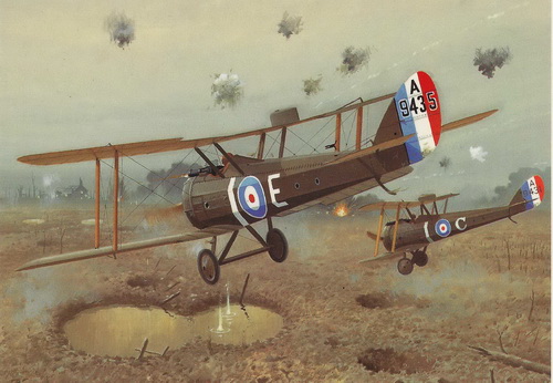 |
| This painting by Brian Knight is featured on the cover of "Windsock Datafile 50 Airco DH5" published by Albatros Productions Inc. A kit box top image for the Lone Start kit could not be found. |
|
AMC DH.5 3-VIEW DRAWING
|
.jpg) |
| This 3-view drawing is reproduced here from the Harleyford publication Fighter Aircraft of World War 1. The DH.5 was a follow-on to the DH.2 pusher biplane. The design was an attempt to incorparate the features of a tractor biplane with a syncronized forward-firing machine gun and a staggered wing-set to provide the pilot with an unobstructed forward view. Howewer, good the forward view, the view to the rear was totally virtually! |
|
THE
MODEL TO BE BUILT
|
.jpg) |
| The model to be built is AMC DH.5 A.9165, flown by Lt. Henry Winslow Woollett, No. 24 Squadron RFC, claiming 4 victories on this aircraft in July 1917. He went on to claim a total of 35 victories during the war. |
|
PHOTO
OF THE
MODEL TO BE BUILT
|
.jpg) |
| This photo is taken from "Windsock Datafile 50 AMC DH.5" by J. M. Bruce and produced by Albatros Productions Ltd. The DH.5 equipped the following RFC Western Front squadrons: 24, 32, 41, 64, and 68. |
.jpg)
|
CONSTRUCTION PHOTO No. 1 |
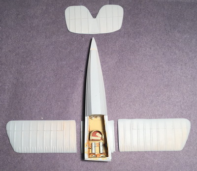 |
| The first item to be addressed is the cockpit interior. The foot skids lead to the rudder bar which were included in the resin kit. Note that the front end needs to be sanded flush. |
|
CONSTRUCTION PHOTO No. 2 |
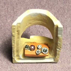 |
| The instrument panel was supplied but the all the gauges were built up from round plastic stock and faced with instrument decals by several makers. |
|
CONSTRUCTION PHOTO No.3 |
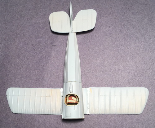 |
| The bottom wing is glued in place with much needed Perfect Plastic Putty. The tail unit (in two pieces) was glued. The one-piece horizontal component came up short on the cut-out of the fuselage. A 1/8-inch piece of the fuselage was cut waya to get the horizontal tail in place so as to clear the placement of the rudder. |
|
CONSTRUCTION PHOTO No.4 |
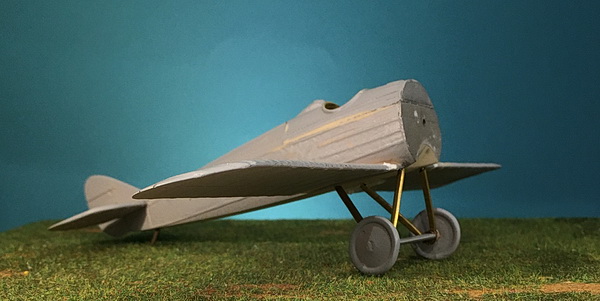 |
| This photo shows the addition of the main landing gear built from brass tube and rod. Struts were carefully matched to both the kit's plastic struts and Windsock Datafile 50 drawings. The kit's resin axle was used. |
|
CONSTRUCTION PHOTO No.5 |
 |
|
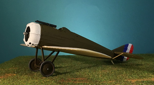
Before painting, I added the Vickers machine gun,
Then, the built-up rotary engine was trial-fitted to
accomodate the cowling. I had to add a thin plastic
square to the outside firewall and glued the engine in
place. When dry, I glued the cowling in place.
Next, I used brass rod for the horizontal tail supports.
Lastly, the tailskid was fashioned from brass tube and rod
as a long piece to fit well into the solid-cast resin
fuselage. Painting of the fuselage is next as shown above. The fuselage, fin, wheel struts, and wheels are painted in my mix of "PC-10" consisting of equal halves of Vallejo 887 US Olive Drab and 983 Flat Earth. Then underside of the fuselage, lower wing, and horizontal tail are painted in Vallejo 976 Buff. The rudder stripes are painted in Vallejo 809 Royal Blue, Andrea XNAC01 White, and Vallejp 947 Dark Vermillion. The cowling was done in Andrea XNAC01 White. All painting required two coats. |
|
CONSTRUCTION PHOTO No.6 |
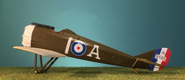 |
| To complete the fuselage at this point, one overcoat of Vallejo Acrylic Satin Varnish was applied for decal adhesion. Fuselage decals came from three different sources in my stash of British decals. The rudder decal in two parts ('A' and '9165') was made in Word and printed on a laser printer. One more poly overcoat to seal the decals was applied. Kit decals were not supplied. |
