|
|
HISTORICAL MINIATURES BY GEORGE GRASSE |
|
|
|
HISTORICAL MINIATURES BY GEORGE GRASSE |
|
|
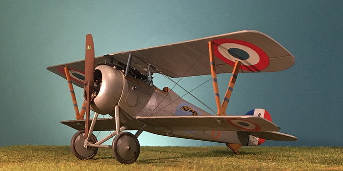
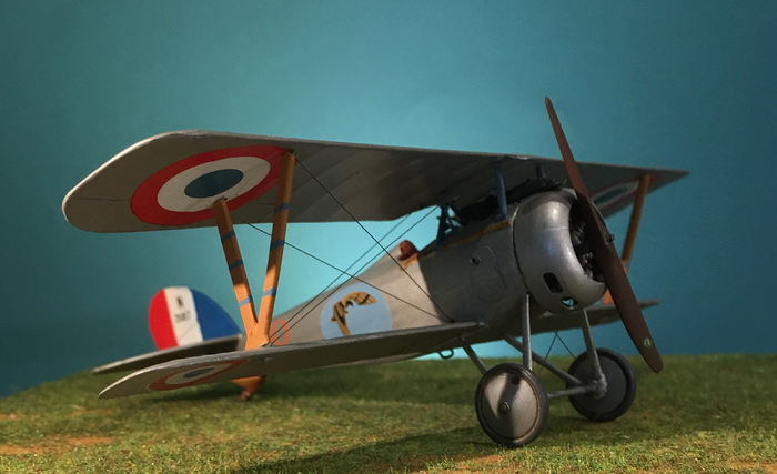
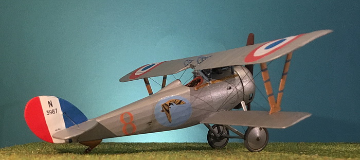
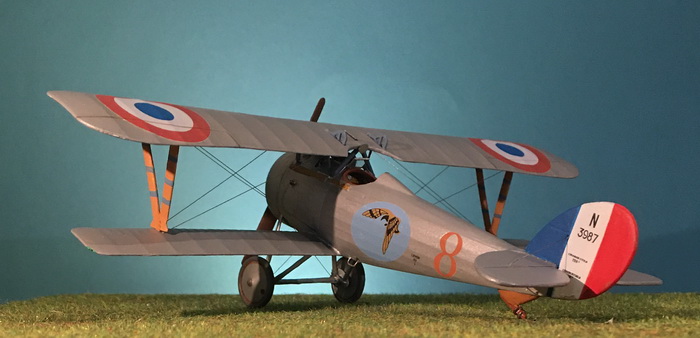
NIEUPORT 24 N.3987, Escadrille N.75, Sous Lieutenant William Herisson, Summer 1917 |
by George Grasse
HI-TECH 1:48 SCALE INJECTION KIT HT4802 of the NIEUPORT 24 (or 27)
|
HI-TECH HT4802 BOX ART
|
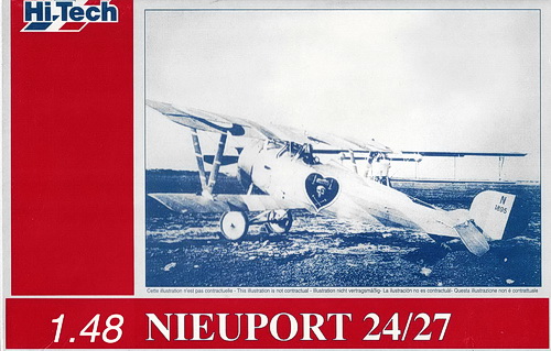 |
| Note that the boxart shown above includes kit parts to build either the Nieuport 24 or Nieuport 27. This is done with two plastic sprues. The first is a standard Eduard Nieuport 17 sprue which includes common parts. The second sprue contains parts exclusive to build either the 24 or 27. |
|
NIEUPORT 24 Three-VIEW DRAWING
|
.jpg) |
| This multi-view drawing is reproduced from the website of Flite Test. The Nieuport 24 was an ongoing development of the basic Nieuport sesquiplane to take larger rotary engines to enhance speed. It derived directly from the Nieuport 23 and was quickly followed by the Nieuport 25 and 27. Finally, with the develop of the Nieuport 28, the wartime series came to end although a Nieuport 29 was built but did not see service to any extent. The success of the Nieuport 24 was attended by difficulties and the production of more successful fighters by other Allies and Central Powers manufacturers. See other sources listed in the Bibliography section at the end of this page. |
|
THE
MODEL TO BE BUILT
|
.jpg) |
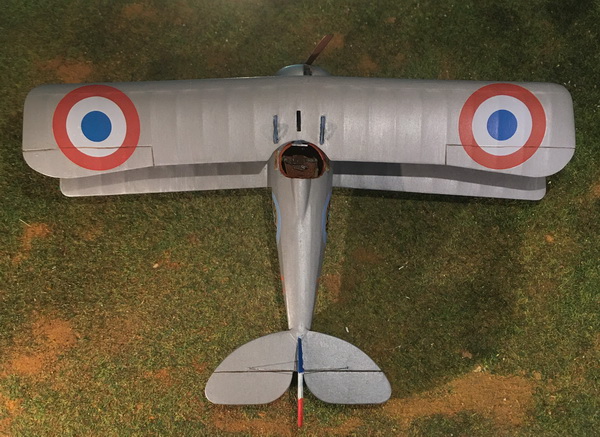
| The model to be built is Nieuport 24 N.3987 of Escadrille N.75 flown by Lieutenant William Herisson (11 victories). It was finished in 'metale enduit' an aluminum powder-based dope. The profile was created by Bob Pearson in The WW1 French Aces Encyclopedia, Volume 4, by David Mechin (see bibliography). The Nieuport 24 was an attempt to further improve the basic Nieuport 17/23 design and led the way shortly to the Nieuport 25/27, none of which competed with the Spad 7 re-equipping French fighter escadrilles. |
%20photo.jpg) Lt Herisson standing by his Nieuport 24 |
|
CONSTRUCTION PHOTO No. 1 |
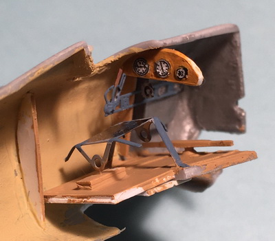 |
| This Hi-Tech kit of the Nieuport 24 or 27, appeared in the days when PE frets made up the greater part of the cockpit interior. The interior as shown above is about half complete. The rudder bar is a plastic kit part. The forward part of the floorboard is a kit plastic part. I added additional plastic to support the PE seat support. So much more to be done. |
|
CONSTRUCTION PHOTO No. 2 |
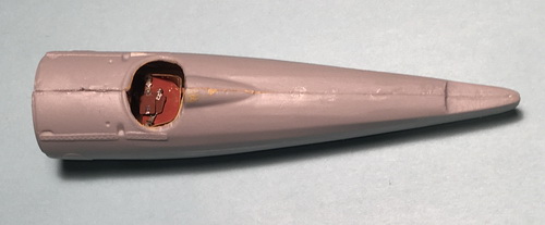 |
| The cockpit was completed and the two halves of the fuselage were glued together as shown. Typically, putty will be applied followed by sanding to minimize seams. |
|
CONSTRUCTION PHOTO No. 3 |
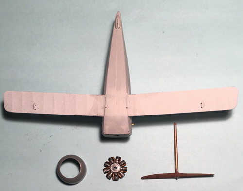 |
| In this photo, parts related to the rotary engine including its propeller and cowling are shown. The kit's Le Rhone rotary engine lacked the induction pipes for each cylinder. I made these from brass rod, painstakingly added one by one. Next, the lower wing was glued into place. The fit was quite poor leaving many gaps. Additionally, the front underside part did not fit at all so I fashioned a piece of plastic stock and glued it into place. To address the gaps, I used fairly large amounts of plastic putty. In fact the process of applying putty, waiting foir it to dry, sanding it and examining the result. It took four iterations of this process to get the underside even and smooth. The two holes are the rear attachment points for the landing gear. At the rear of the fuselage is the kit's resin housing for the tailskid. |
|
CONSTRUCTION PHOTO No. 4 |
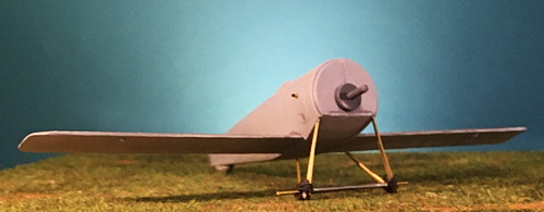 |
| The main landing gear was fashioned from brass tube and rod. Solder wire was used to simulate the bungy cord shock absorbers. The landing gear aerfoil was a piece of lead sheet wrapped around the brass rod axle. |
|
CONSTRUCTION PHOTO No. 5 |
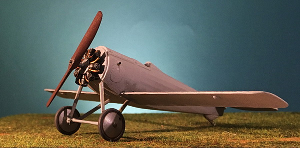 |
| The rotary engine detailing and painting were described in photo panel No.2 above. The engine was fitted over the plastic pin to assure the fit. |
|
CONSTRUCTION PHOTO No. 6 |
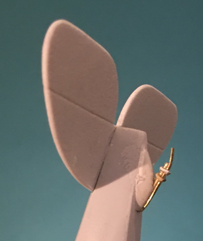 |
| The tail skid was fashioned as near a copy of the original. The main piece was brass rod to which was glued a thin strip of photo etch material to represent the actual skid. Solder wire was used to simulate the bands holding the unit together. |
|
CONSTRUCTION PHOTO No. 7 |
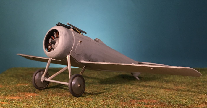 |
| The Nieuport 24's armament is limited to a synchronized Vickers machine gun. A telescopic gunsight was fashioned from brass tube, drilled out with two small holes for support legs, and glued into holes through the plastic top front decking. A left-side expended carteidge casings chute was added (brass). The right-side ammunition feed chute was extended to the top front decking. A fuel access cap made of scrap plastic is just visible at the front leg of the telescope. To be added is a front flash suppression fitting to the front of the Vickers and a windscreen. |
|
CONSTRUCTION PHOTO No. 8 |
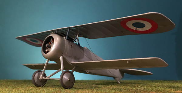 |
| The top wing's underside was prepared for attachment by painting it with two coats of my Vallejo mix of French Enduit Metallise. When dry, it was oversprayed with Vallejo Acrylic Satin Varnish. The kit's decals were not usable so I retrieved large cockades from an Eduard Nieuport 17 kit which is flagged for a Russian ace. Another coat of varnish was applied to seal the decals. The fuselage cabane struts were made from brass tube and rod, then glued to the fuselage. The top wing was glued to these struts. |
|
CONSTRUCTION PHOTO No. 9 |
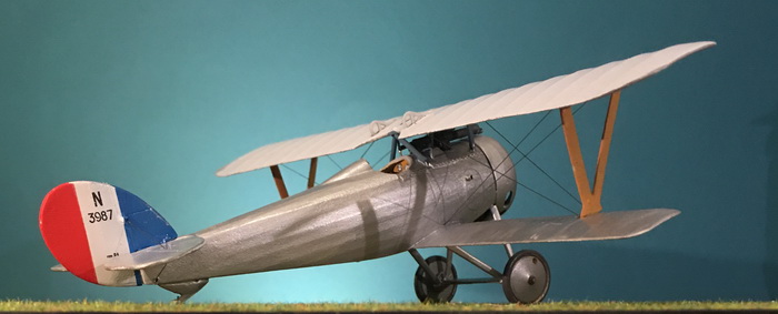 |
| Except for the rudder and landing gear, all other rigging is complete. I used Peddinghaus Nieuport 24 decal sheet specifically for Herisson's N.3987. The wing struts need to have their binding tapes painted in horizon blue. The fuselage was given on coat of paint. |
|
CONSTRUCTION PHOTO No. 10 |
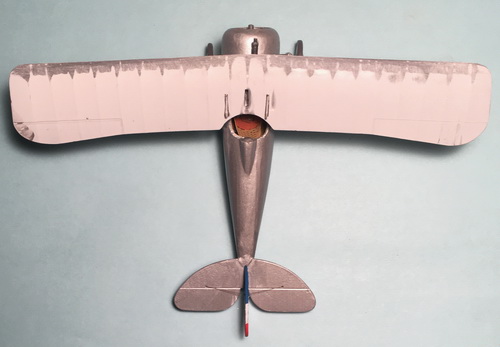 |
| The top wing's leading edge has been sanded down to remove the false ribs. On the upper surface of both wings, the leading edge was now covered by thin plywood. |
|
CONSTRUCTION PHOTO No. 11 |
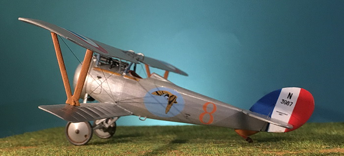 |
| I'm nearly finished. This photo shows the application of all remainihg decals. The decal set I used is Peddinghaus 48.4461 "French Nieuport 24 Aces" (Herisson and Cordoux). This is Herisson's Nieuport 24. Remaining items are windscreen, paint wing strut bindings, and add propeller logo decals. |
|
CONSTRUCTION PHOTO No. 12 |
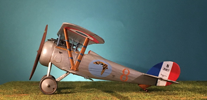 |
| Of the remaining items, painted wing strut bindings and barely visible in this view are propeller logo decals (hand-painted). |
|
CONSTRUCTION PHOTO No. 13 |
 |
|
CONSTRUCTION PHOTO No. 14 |
 |
|
CONSTRUCTION PHOTO No. 15 |
 |
|
CONSTRUCTION PHOTO No. 16 |
 |
|
CONSTRUCTION PHOTO No. 17 |
 |
------------------------------------------- finis ---------------------------------------
Bibliography:
Bailey, Frank W. The French Air Service War Chronology 1914-1918. London: Grub Street, 2001.
Bruce, J. M. Nieuport Fighters, Volume 2, Windsock Datafile Special. Berkhamsted, Herts: Albatros Productions, 1993.
Cooksley, Peter. Nieuport Fighters in Action, Acft Nr. 167. Carrollton, Texas: Squadron/Signal Publications, 1997.
Davilla, James J. Dr. and Arthur M. Soltan. French Aircraft of the First World War. Boulder, CO, Flying Machines Press, 2002.
Franks, Norman. Nieuport Aces of World War 1, Aces Nr. 33. Oxford: Osprey Publishing, 2000
French Escadrille N.75 website page - http://albindenis.free.fr/Site_escadrille/escadrille075.htm
Hayez Lt. Colonel (French Air Force Historical Section), translated by H. D. Hastings. French Escadrilles in World War I. Cross & Cockade (US), Volume 7, Number 3, pages 205-231.
Mechin, David. The WW1 French Aces Encyclopedia, Volume 4. Aeronaut Books, 2021.
GO TO?
14 April 2026
