|
|
HISTORICAL MINIATURES BY GEORGE GRASSE |
|
|
|
HISTORICAL MINIATURES BY GEORGE GRASSE |
|
|
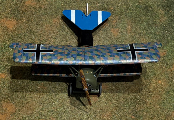
FOKKER D.VI 1661/18, Kurt Seit, Jasta 80b, 1918 |
by George Grasse

EDUARD 1:48 SCALE MULTI-MEDIA KIT BUILT FROM EU8012 FOKKER D.VI
|
EDUARD
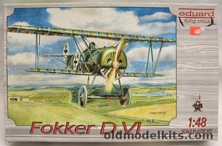
EU8012 FOKKER D.VI BOX ART
|
 |
|
FOKKER D.VI 3-VIEW
|
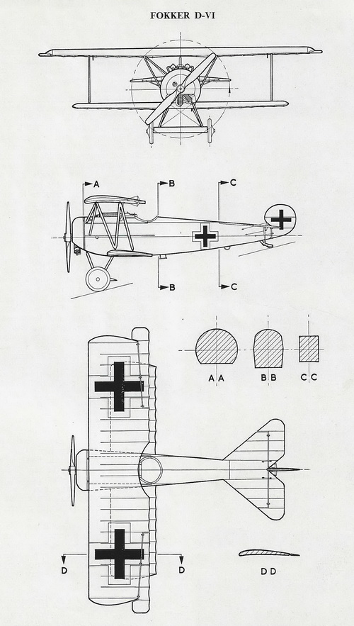 |
| This 3-view drawing taken from Fighter Aircraft of the 1914-1918 War compiled by O. G. Thetford and E. J. Riding, Harleyford Publications, 1954. The Fokker D.VI was an interim step between the Dr.I and the D.VII. Fokker entered both a rotary-engined fighter (the D.VI) and an in-line engined fighter (D.VII) in the January 1918 fighter competition. Although the D.VII was the superior model, production of both was authorized but the D.VI was built in a small quantity compared to the D.VII. Rotary-engined aircraft were quickly approaching their end. |
| THE MODEL TO BE BUILT |
%20x700.jpg) |
| This Fokker D.VI serial 1661/18 flown by Ltn Kurt Seit of Jasta 80b with five confirmed victories and the Silver Wound Badge for four combat wounds. The serial number is arbitrarily assigned based on somewhat known serial numbers issued to Jasta 80b from the collective bibliography I use, which see. |
%20photo.jpg) |
| This photo of Ltn Kurt Seit of Jasta 80b taken P. M. Grosz' Windsock Datafile 84, page 7, shows Seit seated in 1661/18 (my assumed serial numer). Of note is 1) the cowling with a partial piece of the nose art, 2) the name "Fratz", and 3) the border outline that also appears at the rear of the fuselage and encloses the 5-color lozenge amouflage. |
|
CONSTRUCTION PHOTO No.1
|
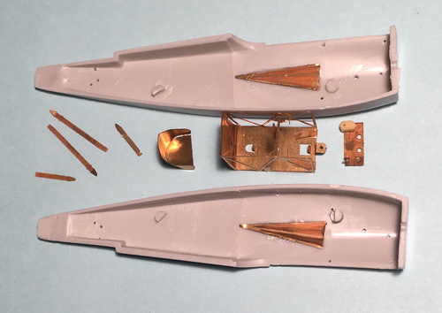 |
| Getting off to a good start for an old Eduard 20th Century kit. Back in those days, cockpit interior was 90% PE material and somewhat difficult to build. Everything is held together with super glue. Several more parts need to added and then painted. |
|
CONSTRUCTION PHOTO No.2
|
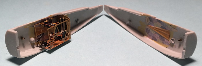 |
| I used a rather faded lozenge decal for the interior but just enough to cover the interior cockpit. This is best seen in the right-hand of the photo. The build up of the cockpit interior is from the usual early pre-2000 Eduard kit using PE components. |
|
CONSTRUCTION PHOTO No.3
|
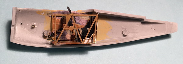 |
| Here is a better view of the right-hand side of the fuselage interior. The fit was quite good and the fuselage halves fit together without gaps. |
|
CONSTRUCTION PHOTO No.4
|
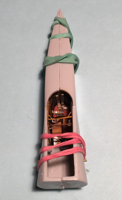 |
| Not much comment needed here except the fuselage halves did not have locating pins but the fit was good. |
|
CONSTRUCTION
PHOTO No.5
|
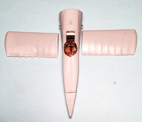 |
| All fuselage seam lines were sanded. The lower wings were a problem: 1) the fit of each of the top and bottom halves was poor; 2) the scalloped rear edges had to be carved away to get the proper depth, so compare the left and right lower wing scalloped edges where the right needs to be cut open; 3) the overall thickness at the trailing edge was too thick. Note the carburetor intake pipes near the front. These were made from brass tubing. |
|
CONSTRUCTION
PHOTO No.6
|
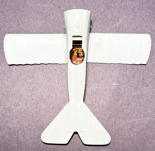 |
| The lower is now attached using brass pins (two fir each wing). The horizontal tail unit is attached to the fuselage with a lot of filler and sanding. Sort of looks like a triplane, yes? |
| CONSTRUCTION PHOTO No. 7 |
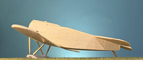 |
| The landing gear and tailskid were added. The tailskid was a simple piece of brass tube with reinforced brass rod cut and sanded to shape. The landing gear was made from 1.5mm OD brass tube with brass rod inserts patterned from the kit's parts and 1:48 scale drawings. The plastic axles were cut off and replaced with brass rod. In preparation for the placement of lozenge decals, the model is pre-painted with two thin coats of Vallejo 837 Pale Sand. |
| CONSTRUCTION PHOTO No. 8 |
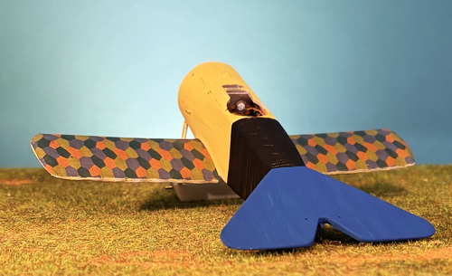 |
| Using Aviattic's 4-color lozenge sheet, I went ahead and covered the top surface of the lower wing. Next, I chose my mix of Vallejo French Colonial Blue but the shade is much too dark. Lastly in this photo I painted the wide black band around the fuselage as shown using my mix of Vallejo Semi-Gloss Black. |
| CONSTRUCTION PHOTO No. 9 |
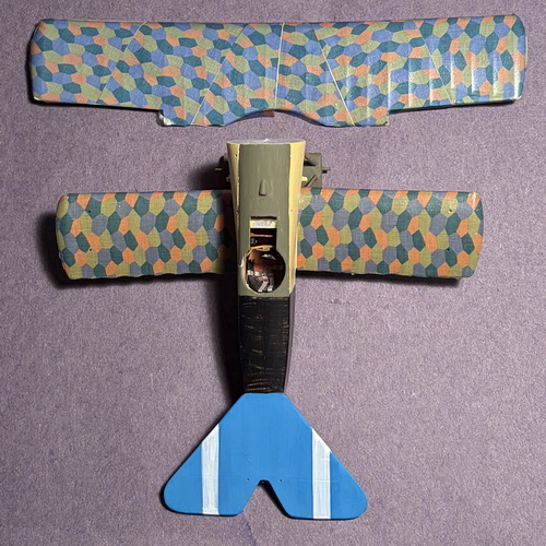 |
| Using more of Aviattic's 4-color lozenge sheet, I continued with the top wing. I cut the strips diagonally sloping in opposite directions. A couple of minor gaps could not be stretched so I''ll apply the rib taps and touchup then. The tail unit color was lightened and looks more like 'Bavarian' blue. I used Peddinghaus decals for this aircraft. My only complaint is the white is somewhat transluscent but that is corrected with white acryllic paint of which one coat has been applied. I painted the top decking in my mix of "Fokker Olive Green". Note that variations in the 4-color decals is probably due to angle of the pieces and that the lower wing has one coat of acryllic applied. |
| CONSTRUCTION PHOTO No. 10 |
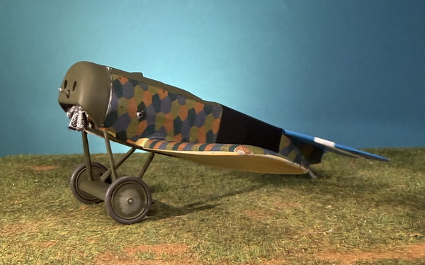 |
| The rotary engine was glued to the firewall using super glue with the cowling in place but not glued to get the prper alignment. The colwing was glued in place using plastic glue and touch up is required around the join. The wheels were painted using my Vallejo mixes for the Fokker olive green, grey-green center, and gray-pink mix for the tires. |
| CONSTRUCTION PHOTO No. 11 |
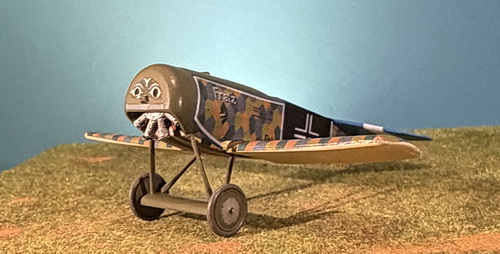 |
| Fuselage decals are added. The comical face on the cowling and the name "Franz" just above the carburator intake pipe personalize this aircraft. Other decals added are weight table, the blue/white fuselage trim (not visible on the rear), and the German cross. |
| CONSTRUCTION PHOTO No. 12 |
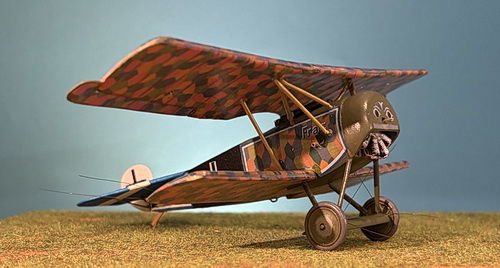 |
| The fuselage struts were built up from 1.3mm brass tubing with brass rod inserts, an exceptionally strong support structure. Also added is the landing gear rigging. The rigging of the tail control surfaces has been started. Eduard "horns" and .006 MFT are used. Just visible on the lower edge of the fuselage is a brass rod representation of the foot step. |
| CONSTRUCTION PHOTO No. 13 |
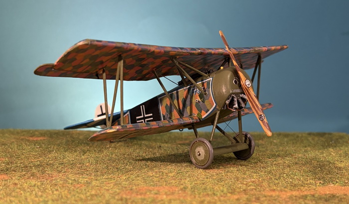 |
| The wing struts were built up from 1.3mm brass tubing with brass rod inserts. The only rigging of note here is the thin piano wire that represents the aileron linkage. The brass object on the cowling top is the gas filler cap. Note the Axial propeller loga decals. |
| CONSTRUCTION PHOTO No. 14 |
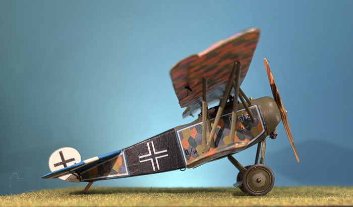 |
| The wing aileron rigging consists of Eduard "horns" and .005 MFT. Barely visible at the front partially blocked by the fuslage struts is the name "Fratz'. |
| CONSTRUCTION PHOTO No. 15 |
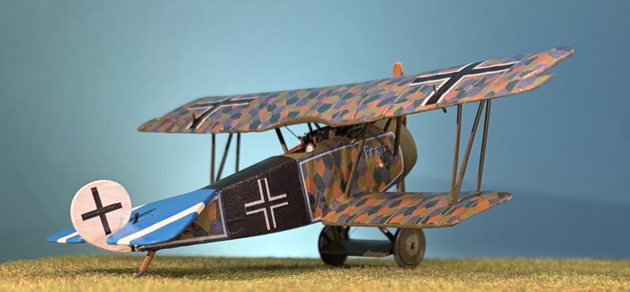 |
| The tail elevator horns show clearly in this photo. I painted all of the "horns" black. |
| CONSTRUCTION PHOTO No. 16 |
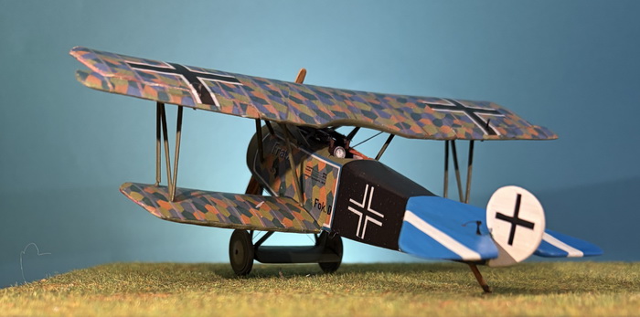 |
| This view shows the large cockpit rev counter, padded butts of the twin Spandau machine guns, the weight table and the truncated Fokker I.D. number. As a closing remark, this was a difficult model to build. |
| CONSTRUCTION PHOTO No. 17 |
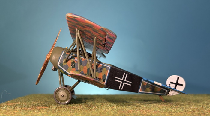 |
| CONSTRUCTION PHOTO No. 18 |
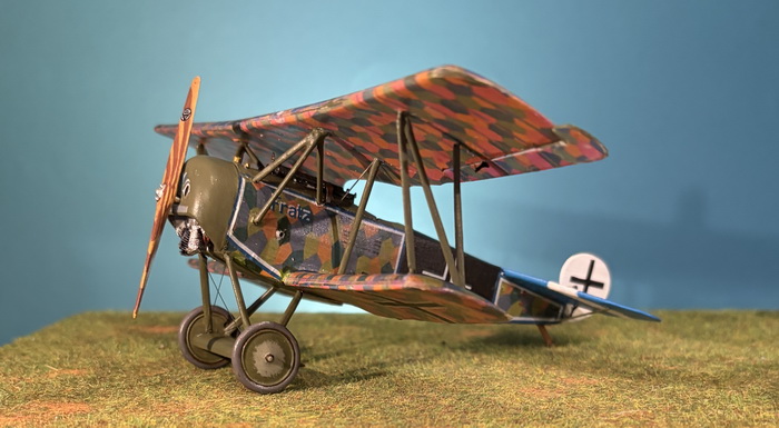 |
| CONSTRUCTION PHOTO No. 19 |
 |
Bibliography:
Bar, Ronny. German Fighters of the Great War, Volume 2. Horncastle, UK: Tempest an imprint of Morton's Books.
Franks, Norman and Frank Bailey & Russell Guest. Above the Lines - A Complete Record of the Fighter Aces of the German Air Service, Naval air Service, and Flanders Marine Corps 1914-1918. London, UK: Grub Street, 1993.
Gray, Peter and Owen Thetford. German Aircraft of the First World War. London: Putnam & Company Limited, 1960.
Herris, Jack and Jorn Leckscheid. Fokker Aircraft of WWI, Volume 5, 1918 Designs, Part 1: Prototype & D.VI. Aeronaut, 2023.
Lamberton, W. M., Compiler, and E. F. Cheesman, Editor. Fighter Aircraft of the 1914-1918 War. Los Angeles, CA: Aero Publishers, 1962.
Grosz, Peter. Fokker D.VI. Berkhampstead, UK: Albatros Productions, 2000.
GO TO?
6 June 2026
