|
|
HISTORICAL MINIATURES BY GEORGE GRASSE WORLD WAR 1 AIRCRAFT IN 1:48 SCALE |
|
|
|
HISTORICAL MINIATURES BY GEORGE GRASSE WORLD WAR 1 AIRCRAFT IN 1:48 SCALE |
|
| ROLAND D.VIa, 1207/18, Jasta 23b, Staffelfuhrer Oblt Otto Kissenberth, Spring 1918 |
by George Grasse

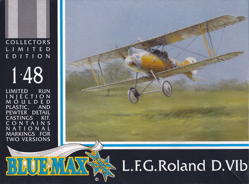
BLUE MAX 1:48 SCALE INJECTION MOLDED KIT BX0117 of the ROLAND D.VIb
|
BLUE MAX BX0117 BOX ART
|
 |
|
ROLAND D.VI THREE-VIEW DRAWING
|
%203-View.jpg) |
| This 3-view drawing is credited to J. D. Carrick or F. Yeoman and appeared in Fighter Aircraft of the 1914-1918 War compiled by W. M. Lamberton and published by Harleyford Publications Limited, page 151. Although this 3-view represents the Roland D.VIb, other sources for detailed drawings are listed in the bibliograpy below. Both versions differed mainly in the 170hp Mercedes D.IIIa for the D.VIa and the 185hp Benz Bz.IIIa for the D.VIb. Smaller details varied as well. |
| THE ROLAND D.VIa TO BE BUILT |
%20x700.jpg) |
|
The model to be built
is the Mercedes-powered Roland D.VIa 1207/18 flown by Jasta
23b Staffelfuhrer Oblt Otto Kissenberth, late winter/early spring 1918.
The serial number is arbitrary. Note that the straight
interplane struts identify Kissenberth's D.VIa as one of the
first built in series 1200-1219/18. If we subtract
serials 1200-1203 as pre-production and testing aircraft,
Kissenberth's D.VIa is in the range 1204-1219/18. The
labeling of the photo below identifies his D.VIa as 1207/18. The fighter competition of January/February 1918 was held and yielded the Fokker D.VII as the aircraft to equip the Jagdstaffeln in the near future. The Albatros D.V and D.Va were clearly out-performed by modern Allied fighters already at the front. The unique Roland D.VI series was available but only in small numbers but with only a marginal improvement over the Albatros fighters. About 350 Roland D.VI (a and b) were built and when the Fokker D.VII's began delivery, both Albatros and Roland fighters were replaced to assume trainer duties. |
| PHOTO OF THE MODEL TO BE BUILT |
.jpg) |
| This photo is taken from Royal Bavarian Jagdstaffel 23 (see bibliography). Oblt Otto Kissenberth's Roland D.VIa is identified as D.1207/18. As Staffelfuhrer, Kissenberth led a high-scoring Jasta in which he reached 19 victories and the Pour le Merite. Photo credit of Kissenberth's portrait below is Blue Max Airmen, v.19, by Lance Bronnenkant, PhD (see also bibliography below). |
.jpg)
.jpg)
| CONSTRUCTION PHOTO #1 |
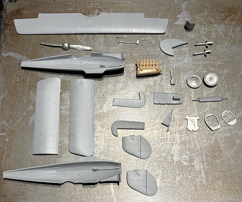 |
| Heading for the paint primer shop. The pale tan colored engine is a replacement. The Blue Max kit is for the Roland D.VIb (Benz engine). The D.VIa which is to be built here takes a Copper State Mercedes D.III above. |
| CONSTRUCTION PHOTO #2 |
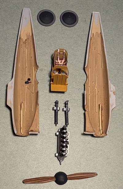 |
| The cockpit and engine are important for the next step which is to glue the fuselage halves together. Seatbelts are by Eduard. Some additional detail was added to the cockpit interior including a compass, throttle, and a couple of gauges. |
| CONSTRUCTION PHOTO #3 |
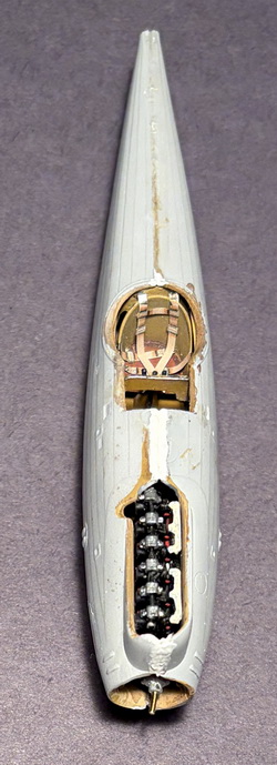 |
| Fuselage halves are joined. The fit was not good at first. It took over a dozen attempts at trimming the cockpit to fit. The substitute Copper State Mercedes engine fit right in. |
| CONSTRUCTION PHOTO #4 |
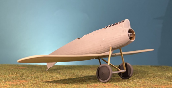 |
| Each half of the lower wing was pinned with two brass rods and glued into corresponding holes in the center pylon on the underside of the fuselage. While the super glue set up, measurements were taken to reproduce the landing gear struts in brass rod and tube. With some minor trimming, the struts were glued in place. I chose to save the kit's axle sub-assembly and cut off the flimsy plastic axle ends. I drilled out holes for brass rod to fit the axle sub-assembly and the wheels. Bungy cord representation will be done using .4 mm soldering wire. The last step at this stage is the fitting of the tailskid. There are no projections or corresponding holes to fit the tailskid. Without them, I expected a weakened connection. I drilled out two holes on the tailskid to match two holes drilled into the underside of the tail. A little super glue to the brass rods and the fit was perfect. |
| CONSTRUCTION PHOTO #5 |
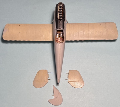 |
| This photo shows the depths to which I had to go to insure that the tail components would be secure. The kit's tail components did not have corresponding pins which I added in the form of brass rod. The tabs on the horizontal tail parts were too shallow. |
| CONSTRUCTION PHOTO #6 |
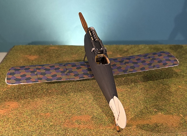 |
| Machine guns are installed. The vertical tail is complete with its white coat of paint and attached tailskid. All of the flying surfaces (lower wing shown above) have been covered in Aviattic 5-color pre-printed camouflage, upper and under surfaces. The fuselage is painted in Vallejo 995 German Grey (flat black was abit too overwhelming). |
| CONSTRUCTION PHOTO #7 |
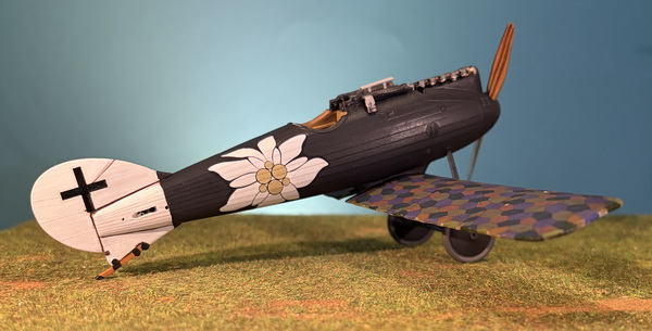 |
| The main accomplishment in this step is the decals applied to the fuselage. The tail crosses came from the kit's decal sheet. The idylweiss motif was taken from the Eduard 8113 Albatros D.V kit. The white primed object between the machine guns is the optical sight made from brass tube into which two holes were drilled for the brass support rods. |
| CONSTRUCTION PHOTO #8 |
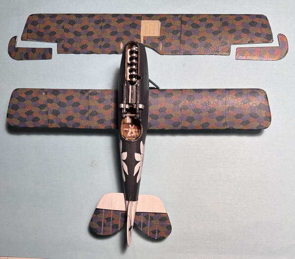 |
| All of the flying surfaces including the underside (not shown) have been covered in pre-printed 5-color fabric. The tail surfaces have their camouflaged rib tapes applied. (note camera distortions using an iPhone) |
| CONSTRUCTION PHOTO #9 |
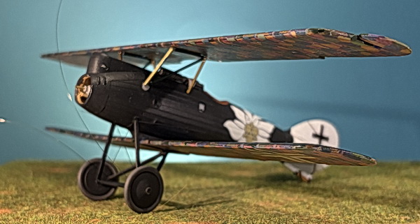 |
| The fuselage struts are made from brass tube and rod. Landing gear rigging is attached and glued in place yet to be trimmed. Both wings have rib tapes painstakingly attached (the least likable aspect of WW1 modeling). Both wings have their cross decals in place. |
| CONSTRUCTION PHOTO #10 |
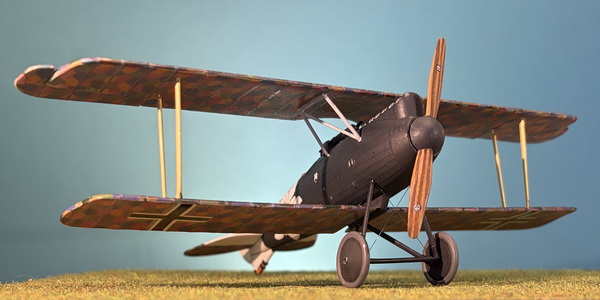 |
| The wing struts are installed. These are made from brass tube (1.4mm OD) and brass rod, to be primed and painted black. |
| CONSTRUCTION PHOTO #11 |
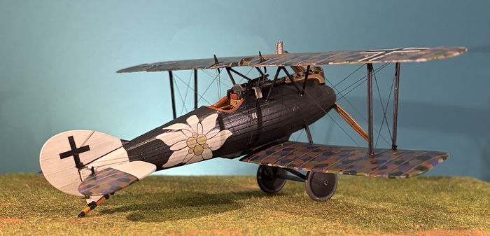 |
| Finished photo showing extension of the tail skid which had broken off during construction and replaced with brass tube and rod insert. All rigging is completed and struts have bee painted Vallejo 995 German Grey. Visible at the forward edge of the top wing is the addition of the water expansion tank. As you will see in the next several photos, the water pipe enters the forward part of the engine side cover. |
| CONSTRUCTION PHOTO #12 |
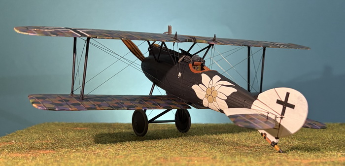 |
| The tail skid is well illustrated here as are the various tail rudder and elevator control horns and wires. he wing struts are installed. |
| CONSTRUCTION PHOTO #13 |
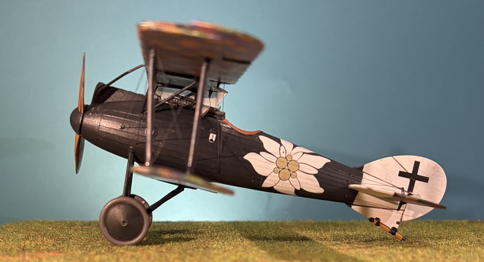 |
| The radiator pipe is shown entering the forward engine side panel and not directly down in the forward part of the engine itself. The Roland D.VIa shows its streamlined profile to good effect. |
| CONSTRUCTION PHOTO #14 |
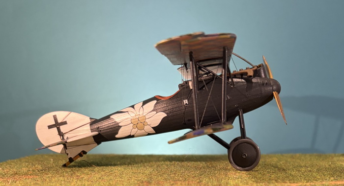 |
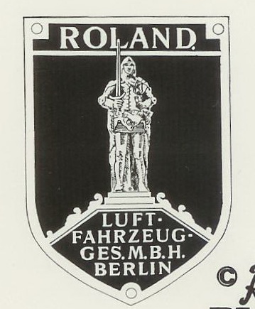
| The kit's six-barrel exhaust pipe was a perfect fit to the engine's exahust ports. The black and white decal near the cockpit is the Roland company's logo. |
| CONSTRUCTION PHOTO #15 |
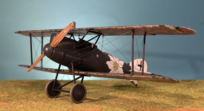 |
| This last photo shows the wing/fuselage riging to good effect. Flying surfaces were covered in Aviattic Pre-printed 5-color lozenge camouflage slightly faded. |
Bibliography:
Bar, Ronny. Ronny Bar Profiles, German Fighters of the Great War, Volume 2 (Roland D.VIa page 158). Horncastle, UK: Tempest an imprint of Morton's Books. ISBN: 9781911704096.
Bronnenkant, Lance J. PhD. The Blue Max Airmen, v.19. Aeronaut Books, 2022.
Gray, Peter and Owen Thetford. German Aircraft of the First World War. London: Putnam & Company Limited, 1962.
Grosz, P. M. Roland D.VI - Windsock Datafile No.37. Berkhamsted, UK: Albatros Productions Ltd, 1993.
Herris, Jack. Roland Aircraft of WWI. Aeronaut Books, 2014. ISBN: 9781935881209.
Lamberton, W. M., Compiler, and E. F. Cheesman, Editor. Fighter Aircraft of the 1914-1918 War. Los Angeles, CA: Aero Publishers, 1962.
Wingnut Wings Roland D.VIa Instruction Manual
GO TO?
15 August 2026
