|
SPAD SA.4 Nr. 79, 30th Corps Detachment, Russian Air Service 1917 |
by George Grasse
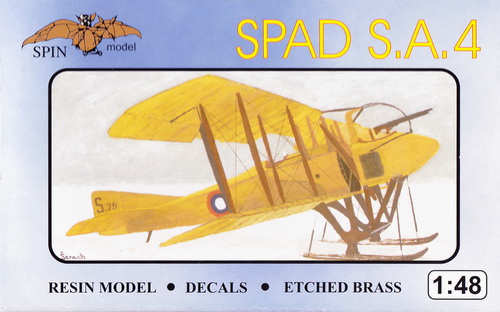
SPIN MODELS 1:48 SCALE RESIN KIT 48004 OF THE SPAD SA.4
|
SPIN MODELS 48004 BOX ART
|
 |
|
SPAD SA.4 THREE-VIEW DRAWING
|
.jpg) |
|
This multi-view drawing is credited Colin Owers and Albatros
Productions from their Mini Datafile on the Spad SA.2 and SA.4 by J.
M Bruce. The Spad SA.4 was the export
(Russia) version of the French SA.2. The major outward
difference being the narrow chord lower wing for the SA.4. As
in France with the SA.2 version, these somewhat odd aircraft were
assigned to flying units as individual aircraft. More reference information is available in the
bibliography section below. |
|
THE
MODEL TO BE BUILT
|
.jpg) |
|
The model to be built is
Spad SA.4 Russian serial number S.79. The aircraft is
finished in the French 'yellow' scheme in which metal parts
had a deeper 'yellow' shade than fabric-covered surfaces.
In this profile, the forward part of the fuselage from the
propeller to the cockpit is
rendered in a darker shade. |
|
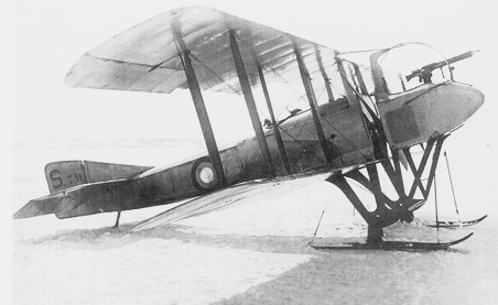
PHOTO OF SPAD SA.4 Nr. S.79
|
 |
|
The above photo is taken from SPAD
Two-Seat Fighters (see bibliography below). During
winter, wheels were removed and skis attached. S.79
was was issued to the Russian 30th Corps Detachment (KAO),
9th Russian Army, Rumanian Front on 22 July 1916.
Earlier, on or about 6 May
1917, the crew of Private Efrietor E. S. Nedzevetsky
(pilot) and Starshiy Unterofitzer Rodin (observer/gunner)
while escorting a photo reconnaisance aircraft shot down
Austro-Hungarian Hansa-Brandenburg C.I serial 63.23 of Flik
1 crewed by Oblt Johann Baumgartner (P) and Ltn d R
Vlastimil Fiala (O) near Gura Gumora who became prisoners. |
| CONSTRUCTION
PHOTO #1 |
%20No.01.JPG) |
| The first task was to address the construction of the fuselage interior. I would have to say that this interior casting is poor at best. The "X" imprint represents interior rigging but in this case the material seems to be construction 2" x 4" in scale. As for reference material, the availability of detailed interior photos withy explanation for nearly all WW1 aircraft is also poor at best. I went ahead and doused the interior with aluminum paint because the outside of the Spad is covered in metal to just beyond the cockpit. I did find a few color photos of a reproduction Spad 7 in work but specific details about the side walls was somewhat difficult to interpret. |
| CONSTRUCTION
PHOTO #2 |
%20No.02.JPG) |
| I made an adjustment to the interior cockpit walls which were aluminum to halfway of the cockpit and then seemed to be fabric from then on. But how do you account for the outside aluminum covering to go beyond the cockpit. I was getting pretty riled up not being able to define the finish of the inside and split the difference on the inside with the forward half in aluminum and the rear half in fabric. I spent far too much time on such a poor interior. So, I plowed ahead and made my own instrument board with Eduard details and scrap plastic. That includes the compass and a leftover decal. Seatbelt straps were taken from Eduard's French WW2 PE sheet. I still have the control column and a bit of wiring to do. |
| CONSTRUCTION
PHOTO #3 |
%20No.03.JPG) |
| The rotary engine was a one-piece resin casting and was painted black then dry-brushed with chrome. As shown, the engine fits into a small compartment and has to be installed before the fuselage halves are glued together. When super glue had set, the seams were filled with Perfect Plastic Putty which dries fairly quickly and then sanded. |
| CONSTRUCTION
PHOTO #4 |
%20No.04.JPG) |
| The next step was to concentrate on the landing gear. This step is necessary before the lower wings can be attached (note the holes for the wing at the top of the landing gear). The attachment of the ski to the axle was deepened to take a slightly larger diameter brass rod. The tail skid was a scrap piece of flattened tubing. The fuselage front plate is directly from the kit's PE sheet. |
| CONSTRUCTION
PHOTO #5 |
%20No.05.JPG) |
| To start with, the tail unit was next. the position of the horizontal tail is critical for alignment and the cut-away space allowed on the model had to be cleaned up and evenly sanded. The horizontal tail was glued in place. When dry, I added the fuselage support struts in small diameter brass rod. The vertical tail unit was next and its position had to be eye-balled carefully. The problem with resin is the use of super glue as an adhesive which sets up quickly. So the vertical tail was carefully positioned and held in place until the glue set. A future wire brace to the vertical fin is planned. The propeller was carefully sanded to eliminate casting pits on the edges. The rotary engine propeller shaft was cut down for an approximate fit and will be finalized when the pulpit is built and fitted. The lower wings had to be carefully held in place while gluing to the top of landing gear. Small brass pins were used for support. |
| CONSTRUCTION
PHOTO #6 |
%20No.06.JPG) |
| The so-called pulpit lies on the ground in the maintenance position. The pulpit is built from two halves. The interior includes the observer's seat and two Lewis gun drum holders (not visible). The bottom (not shown) has an observer's window. The sides are covered with an air-cooling grate on each side. The kit's pulpit struts are replaced with brass and attached to the forward landing gear strut. The fuselage cabane struts are brass and ready for attachment of the top wing. |
| CONSTRUCTION
PHOTO #7 |
%20No.07.JPG) |
| The machine gun support structure was
scratch-built in liew of the kit's PE parts which were flimsy and difficult to handle.
Additionally, the rear protective screen to protect the observer/gunner from the propeller was the kit's PE part. Additional PE parts include the side cooling intake screens and the small connecting plates at the top of the legs. |
| CONSTRUCTION PHOTO #8 |
%20No.08.JPG) |
| The side panels that effectively serve as exhaust for the rotary engine were carefully added to both sides. |
| CONSTRUCTION PHOTO #9 |
%20No.09.JPG) |
| The top wing is installed using brass struts made from 1.4mm tubing with a brass rod insert. Each strut is carefully pounded to an approximation of an aerfoil shape using a small light hammer. |
| CONSTRUCTION PHOTO #10 |
%20No.10.JPG) |
| The model is rigged except for the aileron crank mechanism which will appear at the bottom-inside of the rear outside wing struts. A second coat of my mix of French light yellow has been applied to all fabric covered surfaces. The forward part of the fuselage already has one coat of the darker shade. |
| CONSTRUCTION PHOTO #11 |
%20No.11.JPG) |
| This Spad SA.4 is equipped for winter service. The tail skid is modified to have its own ski which is a simple piece of plastic stock glued to the tail skid and reinforced with a brass rod. |
| CONSTRUCTION PHOTO #12 |
%20No.12.JPG) |
%20No.12a.JPG) |
%20No.12b.JPG) |
| After tail unit work as shown in Photo No.11, above, the model was oversprayed with one coat of Vallejo Acrylic Satin Varnish as a base on which decals will be applied. The decals in the kit disintegrated immediately and were discarded. I anticipated decal problems from old kits and have a copy of Blue Rider's BR507 1/48th scale Russian aircraft decals as shown in this photo panel. The one exception are rudder decals which I made on my laser printer. Another coat of varnish was lightly applied to seal the decals. |
| CONSTRUCTION PHOTO #13a & 13b |
%20No.13a.JPG)
%20No.13b.JPG) |
| The model's last major step was the connection of the fuselage and pulpit. As usual, probelms occurred immediately. For one, the right strut sub-assembly of the pulpit was badly damaged during the process and had to be replaced which is why is appears in its bare brass finish. Second, the pulpit did not line up with the fuselage. The problem was that the extentions on the main landing gear to which the pulpit's legs were to be attached were not long enough. More than likely, the cause was the main landing gear struts were not installed as far forward as possible. The solution was to extend the connection point on the main landing gear's lower forward struts by adding small pieces of plastic stock. You can see now that the alignment is perfect. The brass rod axle for the pulpit's legs is braced by a small diameter brass tube beyond which are the left-over pieces of brass rod that need to be cut off. |
| CONSTRUCTION PHOTO #14 |
%20No.14.JPG) |
| The ski landing gear was straight-forward. Photos of this aircraft showed that the skis were connected to the landing gear axle and had thin rods or cable with what appeared to be coiled springs to absorb landing shock. I used brass rod with electrical fuse wire coiled around part of the rod. |
| CONSTRUCTION PHOTO #15 |
%20No.15.JPG) |
| The front and rear pulpit struts were riggedmodel's last major step was the connection of the fuselage and pulpit. |
| CONSTRUCTION PHOTO #16 |
%20No.16.JPG) |
| This side view shows the arrangement of the ski supporting rods. Also, the aileron linkage is attached to the back of each outside wing strut. |
| CONSTRUCTION PHOTO #17 |
%20No.17.JPG) |
| At the bottom of the rear outside wing strut is the aileron linkage connection in place, a standard feature of Spad aircraft. |
| CONSTRUCTION PHOTO #18 |
%20No.18.JPG) |
| This view shows the aileron linkage on left outside strut. More detail of the ski support rods is visible. |
| CONSTRUCTION PHOTO #19 |
%20No.19.JPG) |
| CONSTRUCTION PHOTO #20 |
%20No.20.JPG) |
COLOR TABLE
| Vallejo VC0856 Ochre
Brown |
Interior wood |
|
Vallejo VC0872 Chocolate Brown |
Wash |
| Vallejo
VC0864 Natural Steel |
Unfinished metal parts |
| Andrea ANAC24 Union
Blue |
Metal fittings and small parts |
| Vallejo Mix French
Light Beige 1 |
All doped linen surfaces (Acelos) |
| Vallejo
Mix French Dark Beige 2 |
All metal and wood
surfaces (Ripolin) |
| Vallejo
VC0856 Ochre Brown |
Struts |
|
1 912 Tan Yellow, 3 parts;
917 Beige, 1 part; 837 Pale Sand, 1 part |
|
2 917 Beige, 3
parts; 837 Pale Sand, 1 part |
------------------------------------------- a
suivre -------------------------------------
Bibliography:
Blume, August G.
The Russian Military Air
Fleet in World War I, volume 2: Victories, Losses, and Awards. Atglen, PA:
Schiffer Military History, 2010.
Bruce, J. M. SPAD S.A-2/S.A-4,
Windsock Mini
Datafile 4. Berkhamstead, UK: Albatros Productions, Ltd, 2000 (reprint).
Conners, John F.
SPAD Fighters in
Action, Aircraft Number 93. Carrollton, Texas. Squadron/Signal
Publications, 1989.
Davilla, James J Dr. and Arthur M. Soltan.
French Aircraft of the First World War. Flying Machines Press, 1997.
Durkota, Alan, Thomas Darcey and Victor
Kulikov. The Imperial Russian Air Service: Famous Pilots and Aircraft of
World War I. Flying Machines Press, 1995.
Herris, Jack.
SPAD Two-Seat Fighters
of World War I, Great War Aircraft in Profile No. 7. Flying Machines
Press, 2005.
Lamberton, W. M., Compiler, and E. F. Cheesman,
Editor. Fighter Aircraft of the 1914-1918 War.
Los Angeles, CA: Aero Publishers, 1962.
GO TO?
27 February 2026
