|
|
HISTORICAL MINIATURES BY GEORGE GRASSE |
|
|
|
HISTORICAL MINIATURES BY GEORGE GRASSE |
|
|
DAYTON-LIBERTY DH-4 OF THE 50th AERO SQUADRON, U. S. AIR SERVICE, 1918 |
by George Grasse

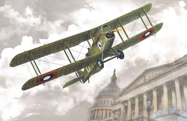
RODEN 1:48 SCALE PLASTIC INJECTION MOLDED KIT RO.414 OF THE LIBERTY DH-4
|
RODEN KIT RO0414 BOX ART
|
 |
|
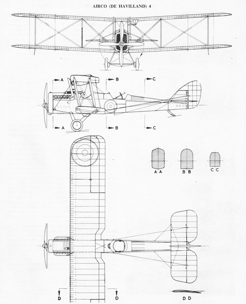
DH-4 3-VIEW DRAWING
|
 |
|
This 3-view drawing is credited to J. D. Carrick or F. Yeoman and appeared in Reconnaissance & Bomber Aircraft of the 1914-1918 War compiled by W. M. Lamberton and published by Harleyford Publications Limited. The British-designed but American-built DH-4 was a two-seat airplane intended to equip several U. S. Air Service bombing squadrons during America's active participation on the Western Front in the second half of 1918. The intended bomber was actually the British DH-9A or the French Breguet 14.B2 neither of which were allowed to be licensed-built by their respective governments. The older DH-4 design was made available and production began at several plants in the U. S. The intended reconnaissance aircraft of the USAS was to be the Salmson 2.A2 but not enough were made available by the French government to equip American squadrons. Initially, while the first Salmsons were being readied, three USAS squadrons were equipped with the obsolete French-built Sopwith 1: the 88th and 99th Aero Squadrons flew the 1.A2 reconnaissance version but the 90th Aero Squadron flew the 1.B2 bomber version which was altered to the 1.A2 configuration). Eventually, Salmson 2.A2s were made available to these squadrons and also to a few others but at a slow pace such that the Dayton-Liberty DH-4, now rolling off of American production lines, was lassoed into the role of reconnaissance. Thus, the 50th Aero Squadron, among others, was equipped with the American Liberty-built DH-4. |
|
THE
MODEL TO BE BUILT
|
%20profile%2001.jpg) |
| The model to be built is "red 6" of the 50th Aero Squadron flown by 1/Lt. Harold E. Goettler (P) and 2/Lt Erwin W. Bleckley (O), KIA 6 October 1918, during a most daring attempt to locate and re-supply the "Lost Battalion". Both were awarded the Medal of Honor posthumously. The image is taken from page 725 of American Military Aircraft 1908-1919 by Robert B. Casari, color profile by Juanita Franzi or Bob Pearson. |
l.jpg)
|
CONSTRUCTION PHOTO No. 1
|
%20Liberty%20DH-4%2050th%20Aero%20Sqdn%2001.jpg) |
| FUSELAGE BEGINNINGS: This is the first step towards fuselage construction. Most of the basic kit parts are installed. The darker shade of the interior is Vallejo 981 Orange Brown. The lighter shade is Vallejo 856 Ochre Brown. The interior was then washed with thinned out Vallejo 876 Chocolate Brown. The trim wheel, camera, and throttle are semi-gloss black. The engine cylinder blocks are a mix of semi-gloss black and Vallejo 864 Natural Steel. The instrument panel is 856 Ochre Brown with semi-gloss instruments trimmed in Natural Steel. The observer's seat is a round wooden seat fixed to a natural steel base. |
|
CONSTRUCTION PHOTO No.
2
|
%20Liberty%20DH-4%2050th%20Aero%20Sqdn%2002.jpg) |
|
FUSELAGE JOINED AND WING WORK:
A number of small details not supplied in the kit were added
to the fuselage interior: spare Lewis ammunition drums,
boxes to hold photo plates, and miscellaneous cockpit
components. The fuselage was then joined and allowed
to dry thoroughly. The lower wing and horizontal tail
surface was glued in place and, while drying, checked for
alignment. When these were all dry, it was decided to paint
the under surfaces of the wings and horizontal tail.
Now, herein lies the problem. The early Liberty DH-4s
are variously described as being painted and olive drab on
the top surfaces: wings, horizontal tail, and the top
decking of the fuselage. All remaining surfaces were
painted in the so-called "cream" shade, used because
available paint stocks for olive drab wee limited. The
"cream" shade has been found to have several interpretations
depending on your preferred source. Alan Toelle gives
a convincing presentation for a grayish-cream based on the
examinations of extant samples, though the sample size was
quite limited since surviving USAS Liberty DH-4 fabrics are
scarce. When combined with the written observation of
observers who recorded their impressions during the was
years, the cream color takes on a number of shades all of
which can be explained away as different paint batches,
lighting conditions, time of day, weathering of the
aircraft, and fading of the paint. So, what shades to use? The aircraft depicted was in constant use during Meuse-Argonne campaign and had been hat the front for several weeks involved in several missions. It is possible that the "cream" effect of the original paint had, by now, morphed into a faded, pale buff but still showing signs of its "cream" origins. I have chosen from four difference paints and the one that exhibits a bit of "cream". and a bit of "buff", and a bit of "pale gray" is Model Master Enamel Paint No. 1706 "Sand". I know that it doesn't compare with the Juanita Franzi and Bob Pearson pale gray but I like my interpretation. |
|
CONSTRUCTION PHOTO No.
3
|
%20Liberty%20DH-4%2050th%20Aero%20Sqdn%2003.jpg) |
| FUSELAGE RADIATOR AND LANDING GEAR: The front end of the fuselage was slightly out of alignment and had to be re-glued on the right front. The radiator did not fit onto the front so some sanding was required to get it to fit. The landing gear was easy but lacked the depth and thickness of the gluing pins for strength. I will consider using piano wire for the landing gear rigging to bolster the struts. |
|
CONSTRUCTION PHOTO No.
4
|
%20Liberty%20DH-4%2050th%20Aero%20Sqdn%2004.jpg) |
| MORE FUSELAGE DETAILS: The tailskid is in place. The the kit's plastic elevator struts were replaced with brass rod. The fuselage wing struts have been added and exhaust pipes have been installed. The landing gear attachment was re-worked. The plastic glue did not hold the gear in place. I drilled out the top of each strut with a No. 76 drill bit and installed piano wire. The strut holes in the bottom of the fuselage were opened and checked for depth to accept the elongated piano wire and the unit was attached using super glue. |
|
CONSTRUCTION PHOTO No.
5
|
%20Liberty%20DH-4%2050th%20Aero%20Sqdn%2005.jpg) |
| UPPER WING RIGGING - The underside of the top wing is rigged using charcoal .005 monofilament thread. The one exception are the aileron wires to be rigged after the wings have been assembled and fully rigged. I used the photos and three-view drawings in Windsock Datafile 101 as a guide. The flying wires are double-rigged. The underside of the wing is painted in Model Master 1706 Sand. |
|
CONSTRUCTION PHOTO No.
6
|
%20Liberty%20DH-4%2050th%20Aero%20Sqdn%2006.jpg) |
| PAINTING - The upper surfaces of the wings, tail plane, and fuselage are painted in Misterkit MKUSA3 U. S. Air Service Olive Drab. This shade appears a bit too green - to me it should be a bit browner. However, aside from all of the articles on Liberty DH.4 olive drab and reproduction color chips, there is not a consensus as to the true shade. So, I'll let the Misterkit version stand for now. The lower portion of the fuselage was painted in Model Master 1706 Sand. I don't recall now where I read the reason for this peculiar approach to camouflage but, as I recall, it was intended to facilitate 'sky' camouflage when the aircraft was viewed in profile and/or there was a shortage of olive drab and an excess of the lighter dope. |
|
CONSTRUCTION PHOTO No.
7a
|
%20Liberty%20DH-4%2050th%20Aero%20Sqdn%2007a.jpg) |
| FUSELAGE DETAILS - PART 1: The rudder which runs along the fuselage all the way forward to an entry point adjacent to the pilot's control stick in the cockpit. The elevator horn is missing on the left side and needs to be replaced before rigging can be completed. The "Little Dutch Girl" insignia of the 50th Aero Squadron was copied from an image appearing in Medal of Honor Aviators of World War I (Volume 1). It was sized down first and then a right-side image was made by flipping the image in my photo software. The two images were loaded onto a work document and printed on clear decal paper. The red '6' image was done in two sizes: one size for the fuselage as shown and another size for the wings (not shown). The closest font style used was Arial, size 48 for the fuselage and size 72 for the wings. The small serial number '32517' on both sides of the rudder and the 'Life Here' markings (two per side) are Calibri (Body) font size 4. The wind generator (fuselage left side opposite the observer's cockpit) is from the kit put it has a brass pin for insertion into the fuselage and a single smaller brass rod passing through its body and bent backwards to simulate the support structure. Note the strut fittings taken from Eduard's turnbuckle PE sheet. |
|
CONSTRUCTION PHOTO No.
7b
|
%20Liberty%20DH-4%2050th%20Aero%20Sqdn%2007b.jpg) |
| FUSELAGE DETAILS - PART 2: The pilot's forward-firing twin-Marlin machine guns (barely visible) are installed and painted with a mix of black, natural steel, and a touch of metallic blue. The under carriage rigging is installed on the front and rear struts. The propeller and wheels are added for looks, for now. |
|
CONSTRUCTION PHOTO No.
8
|
|
|
| TAIL RIGGING: This photo tries to show the somewhat complicated rigging of the rudder and elevator control wires. Since I was missing one of the kit's rudder control horns (shown into front of the "Little Dutch Girl" insignia at the bottom of the fuselage), I had to make a matching pair. I used discarded photo-etch brass t0 cut the basic shape. I drilled out the ends and, with a slightly large bit, drilled out the center. I cut off the nubs where the plastic version was to be glued and drilled out holes on both sides. I passed a brass rod through these holes, cut them to length, and attached the make-shift horns with super glue. The rudder control wires pass just under the elevator horns though a guide loop and into the fuselage near the wing root. |
|
CONSTRUCTION PHOTO No.
9
|
|
|
| TOP WING ATTACHED AND RIGGED: The top wing was first glued to the fuselage struts. The wing struts were glued next starting with the inboard pair on each side followed by the outboard pair. The time consuming stage was the rigging. All of the rigging was pre-glued to the underside of the top wing (see panel 5 above). I decided not to use PE turnbuckles and resorted to just passing each rigging line through a simple hole, attaching a weight to the end, and gluing in place. The inboard bays were rigged first followed by the outboard bays. I finished up by gluing the fuselage strut rigging and drift wires. Aileron control wires will be done after painting. |
|
FINISHED PHOTO No. 10a
|
%20Liberty%20DH-4%2050th%20Aero%20Sqdn%2010a.jpg) |
|
FINISHED PHOTO No. 10b
|
%20Liberty%20DH-4%2050th%20Aero%20Sqdn%2010b.jpg) |
|
FINISHED PHOTO No. 10c
|
%20Liberty%20DH-4%2050th%20Aero%20Sqdn%2010c.jpg) |
|
FINISHED PHOTO No. 10d
|
%20Liberty%20DH-4%2050th%20Aero%20Sqdn%2010d.jpg) |
|
FINISHED PHOTO No. 10e
|
%20Liberty%20DH-4%2050th%20Aero%20Sqdn%2010e.jpg) |
|
FINISHED PHOTO No. 10f
|
%20Liberty%20DH-4%2050th%20Aero%20Sqdn%2010f.jpg)
|
%20Poster%20'Consider'.jpg)
Bibliography:
Boyne, Walter J. de Havilland DH-4. Washington, D.C: Smithsonian Institution Press, 1984
Durkota, Alan E. Medal of Honor Aviators of World War One, Volume 1. Stratford, CT: Flying Machine Press, 1998.
Maurer, Maurer, editor. The U.S. Air Service in World War I, four volumes. U. S. Government Printing Office, 1979.
Gutman, Jon. American DH4, Windsock Datafile 101. Berkhamsted. Hertfordshire, UK, 2003.
Lamberton, W. M., Compiler, and E. F. Cheesman, Editor. Reconnaissance & Bomber Aircraft of the 1914-1918 War. Los Angeles, CA: Aero Publishers, 1962.
U. S. Air Service 50th Aero Squadron: http://everything.explained.today/50th_Attack_Squadron/
GO TO?